ABUS AZ4299 Terxon SX Base Kit with sounder Installation User Manual
Page 90
14
UK
10.2 Control
units
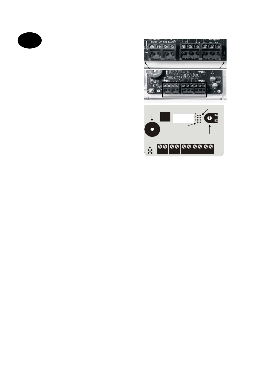
The burglar alarm panel can operate with up to four
control units connected via a BUS.
The control units can be connected as a ring or star to
the alarm centre. Connect the control unit as follows:
To next control unit / alarm centre
Terminal connector strip: 0V
To next control unit / alarm centre
Terminal connector strip: 12V
To next control unit / alarm centre
Terminal connector strip: CLK (Clock)
To next control unit / alarm centre
Terminal connector strip: DATA (Data)
The length of the databus must not exceed 200m. For
connecting the control units, use a cable with a wire
diameter of min. 0.6mm.
Other devices that can be connected to the control
units:
ET: A switch for manual ending of exit delay time. The
contact is normally open (NO) and must be closed to
activate.
Ext. Tamper: Additional input on control unit to which
an external tamper contact (NC) can be connected.
The contact must be opened to trigger a tamper
alarm.
PANIC I/P (from panel version 2.04.0151): There
you can connect a panic button.
1
2
3
4
5
6
7
NOTE: The connection cables must be inserted in
the clamps from above
.
Coding of control units:
Control unit 1:
Jumper not connected
Control units 2–4:
Jumper connected accordingly to
the pin numbers 2, 3, or 4.
Background lighting:
Background lighting on: Jumper connected.
coding of control units
background lighting
volume beeper
tamper contact
beeper
1
2
3
4
5
6
7