Bell & Gossett P2001487 Technologic Pump Controller User Manual
Page 80
Digital inputs
Programmable digital inputs
4 (6)
1)
Terminal number
18, 19, 27
1)
, 29
1)
, 32, 33,
Logic
PNP or NPN
Voltage level
0-24 V DC
Voltage level, logic'0' PNP
<5 V DC
Voltage level, logic'1' PNP
>10 V DC
Voltage level, logic '0' NPN
2)
>19 V DC
Voltage level, logic '1' NPN
2)
<14 V DC
Maximum voltage on input
28 V DC
Pulse frequency range
0-110 kHz
(Duty cycle) Min. pulse width
4.5 ms
Input resistance, R
i
approx. 4 kΩ
Analog inputs
Number of analog inputs
2
Terminal number
53, 54
Modes
Voltage or current
Mode select
Switch S201 and switch S202
Voltage mode
Switch S201/switch S202 = OFF (U)
Voltage level
-10 to +10 V (scaleable)
Input resistance, R
i
approx. 10 k
Ω
Max. voltage
±20 V
Current mode
Switch S201/switch S202 = ON (I)
Current level
0/4 to 20 mA (scaleable)
Input resistance, R
i
approx. 200
Ω
Max. current
30 mA
Resolution for analog inputs
10 bit (+ sign)
Accuracy of analog inputs
Max. error 0.5% of full scale
Bandwidth
20 Hz/100 Hz
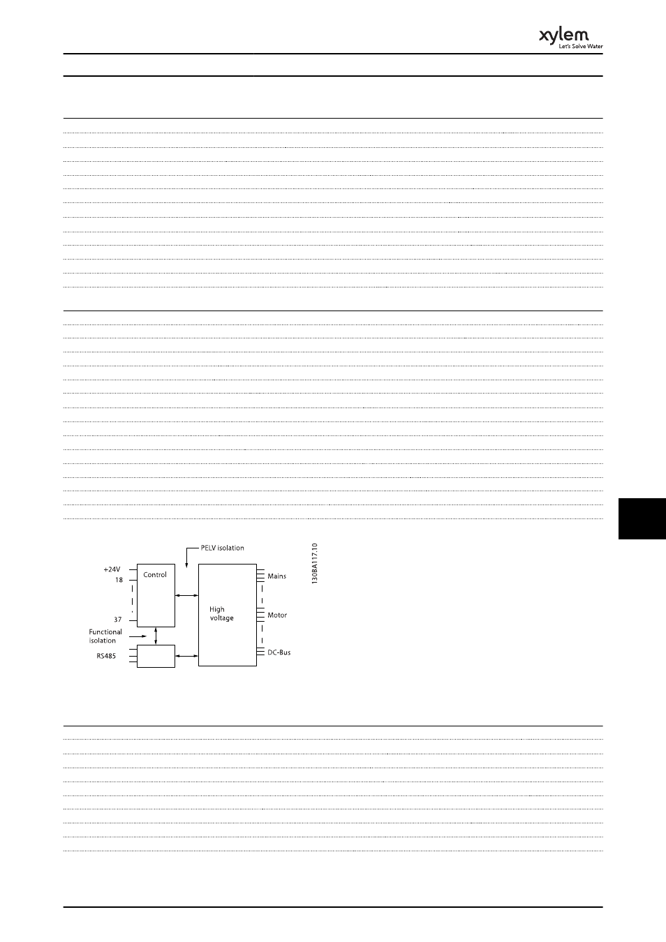
The analog inputs are galvanically isolated from the supply voltage (PELV) and other high-voltage terminals.
Illustration 10.1 PELV Isolation
Pulse
Programmable pulse
2/1
Terminal number pulse
29
1)
, 33
2)
/ 33
3)
Max. frequency at terminal 29, 33
110 kHz (Push-pull driven)
Max. frequency at terminal 29, 33
5 kHz (open collector)
Min. frequency at terminal 29, 33
4 Hz
Voltage level
see 10.2.1 Digital Inputs
Maximum voltage on input
28 V DC
Input resistance, R
i
approx. 4 k
Ω
Pulse input accuracy (0.1-1 kHz)
Max. error: 0.1% of full scale
Specifications
77
10
10