Bell & Gossett P2001487 Technologic Pump Controller User Manual
Page 48
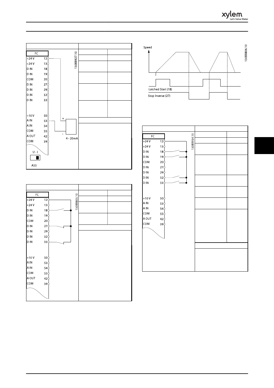
Parameters
Function
Setting
6-12 Terminal 53
Low Current
4 mA*
6-13 Terminal 53
High Current
20 mA*
6-14 Terminal 53
Low Ref./Feedb.
Value
0 Hz
6-15 Terminal 53
High Ref./Feedb.
Value
50 Hz
* = Default Value
Notes/comments:
Table 6.4 Analog Speed Reference (Current)
Parameters
Function
Setting
5-10 Terminal 18
Digital Input
[9] Latched
Start
5-12 Terminal 27
Digital Input
[6] Stop
Inverse
* = Default Value
Notes/comments:
If 5-12 Terminal 27 Digital Input
is set to [0] No operation, a
jumper wire to terminal 27 is
not needed.
Table 6.5 Pulse Start/Stop
Illustration 6.1 Latched Start/Stop Inverse
Parameters
Function
Setting
5-10 Terminal 18
Digital Input
[8] Start
5-11 Terminal 19
Digital Input
[10]
Reversing*
5-12 Terminal 27
Digital Input
[0] No
operation
5-14 Terminal 32
Digital Input
[16] Preset
ref bit 0
5-15 Terminal 33
Digital Input
[17] Preset
ref bit 1
3-10 Preset
Reference
Preset ref. 0
Preset ref. 1
Preset ref. 2
Preset ref. 3
25%
50%
75%
100%
* = Default Value
Notes/comments:
Table 6.6 Start/Stop with Reversing and 4 Preset Speeds
Application Set-Up Examples
45
6
6
- 10 001 247 R3 TechnoForce Package System (36 pages)
- 10 001 265R5 TechnoForce Pump Controller (76 pages)
- 10-001-275 XLS Integrated Pump Controller (57 pages)
- 10-001-278 XLS Integrated Pump Controller (44 pages)
- 176R0649C Technologic 502 Series Pump Controller (74 pages)
- 193 TECHNOVAR VARIABLE SPEED PUMP CONTROLLER AND INTEGRATED AJUSTABLE FREQUENCY DRIVE (78 pages)
- 210667C Z-4 (2 pages)
- 210668B Z-4B (6 pages)
- 211013D PSE 800 M Low Water Cut-off (20 pages)
- MM 217L Series 150S and 157S Low Water Cut-Offs/Pump Controllers (12 pages)
- Iron & Bronze Booster Pumps Series 100 (4 pages)
- P2000642B i-ALERT Condition Monitor (18 pages)
- P80922A Zone Trol Pump Controller ZT-1X (4 pages)
- P80925B Zone Trol Zone Pump Controller ZT-2 (6 pages)
- S11574C Heat Transfer Package with Air Separation (8 pages)
- S11865A TECHNOLOGIC 1100 SERIES PUMP CONTROLLER (4 pages)
- 70E Multiple Pump & Control Pressure Booster Systems (28 pages)
- S12260 R4 Genuine Bell & Gossett Replacement Seal Kit (1 page)
- S12596B Technologic 350 Pump Controller (24 pages)
- S13213A MiniBooster Pumping Package (10 pages)
- S13641B Technologic 5500 Series Pump Controller (38 pages)
- S13654B Technologic 5500 Series Pump Controller (31 pages)
- S14141B 70X Multiple Pump Pressure Booster Systems (12 pages)
- S14333 Technologic 5500 Series ZoneSav Controller (38 pages)
- S14334B Technologic 5500 Series Variable Primary Pump and Valve Controller (54 pages)
- S14362C Glycol Make-up Unit (10 pages)
- S14367B Technologic Constant Speed Pump Controller (44 pages)
- 6 71 075 003A Autocirc Instant Hot Water Pump Models e3-4/BDPQC (8 pages)
- 6 71 075 110A The ecocirc auto/vario Series Pumps (4 pages)
- 6 71 075 111A Autocirc Instant Hot Water Pump Model ecocirc 23 5 ACT (8 pages)
- 6 71 075 114A Series e3 SC Solar Circulators (6 pages)
- 6 71 075 115A LS Condensate Removal Pump (6 pages)
- 6 71 075 141B ecocirc wireless Potable Hot Water Recirculation Kit (28 pages)
- A 00 091 365A Series e3 4/e3 6 Instant Hot Water Recirculating Systems (6 pages)
- A 00 091 391A Automatic Plug-In Timer for e³-4/e³-6 Circulators (2 pages)
- A91590B DB-3/4″ Differential By-Pass Valve 3/4″ x 3/4″ NPT Male Connections Operational Limits (2 pages)
- A91591 Number 98 High Capacity Air Vent 1/2″ Female NPT Connection Operational Limits (3 pages)
- AC8584D Series HSCS Base Mounted Centrifugal Pumps (32 pages)
- IM207R00 Series 3530 (24 pages)
- IM228R04 e-SV (64 pages)
- MN 414 AC Submersible Pump Motors (16 pages)
- P0002560 Wireless Module and RS-485 Module (8 pages)
- P15758C Replacing the Bearing Frame Assembly or Pump Shaft (5 pages)
- P15776H Little Red Booster Pumps (4 pages)