Bell & Gossett P2001487 Technologic Pump Controller User Manual
Page 56
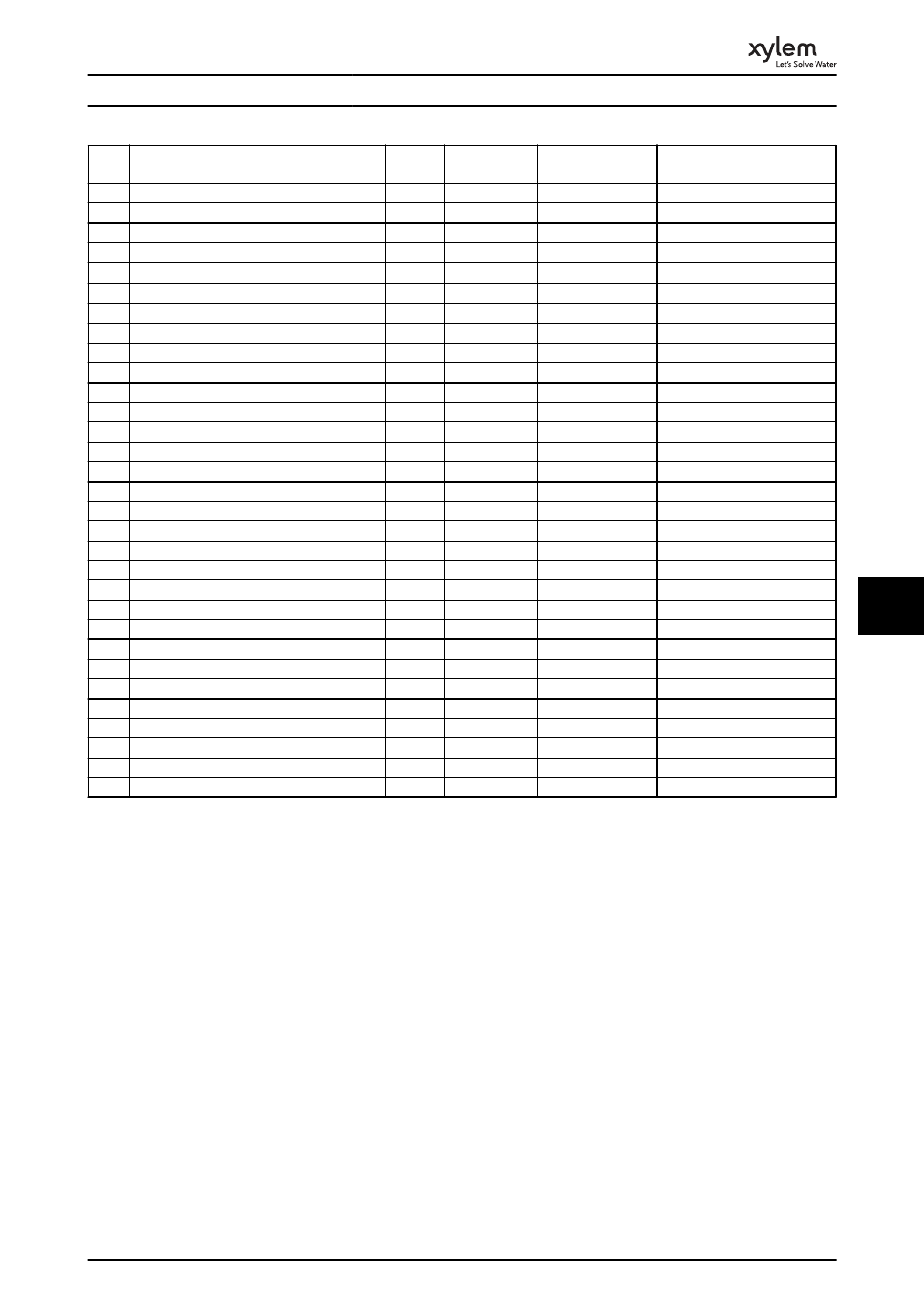
No.
Description
Warnin
g
Alarm/Trip
Alarm/Trip Lock
Parameter Reference
66
Heat sink Temperature Low
X
67
Option Configuration has Changed
X
69
Pwr. Card Temp
X
X
70
Illegal FC configuration
X
71
PTC 1 Safe Stop
X
X
1)
72
Dangerous Failure
X
1)
73
Safe Stop Auto Restart
76
Power Unit Setup
X
77
Reduced Power Mode
79
Illegal PS config
X
X
80
Drive Initialized to Default Value
X
91
Analog input 54 wrong settings
X
92
NoFlow
X
X
22-2*
93
Dry Pump
X
X
22-2*
94
End of Curve
X
X
22-5*
95
Broken Belt
X
X
22-6*
96
Start Delayed
X
22-7*
97
Stop Delayed
X
22-7*
98
Clock Fault
X
0-7*
201
Fire M was Active
202
Fire M Limits Exceeded
203
Missing Motor
204
Locked Rotor
243
Brake IGBT
X
X
244
Heatsink temp
X
X
X
245
Heatsink sensor
X
X
246
Pwr.card supply
X
X
247
Pwr.card temp
X
X
248
Illegal PS config
X
X
250
New spare parts
X
251
New Type Code
X
X
Table 8.1 Alarm/Warning Code List
(X) Dependent on parameter
1)
Cannot be Auto reset via 14-20 Reset Mode
The warning/alarm information below defines each
warning/alarm condition, provides the probable cause for
the condition, and details a remedy or troubleshooting
procedure.
WARNING 1, 10 Volts low
The control card voltage is below 10 V from terminal 50.
Remove some of the load from terminal 50, as the 10 V
supply is overloaded. Max. 15 mA or minimum 590
Ω.
This condition can be caused by a short in a connected
potentiometer or improper wiring of the potentiometer.
Troubleshooting
Remove the wiring from terminal 50. If the warning clears,
the problem is with the customer wiring. If the warning
does not clear, replace the control card.
WARNING/ALARM 2, Live zero error
This warning or alarm only appears if programmed by the
user in 6-01 Live Zero Timeout Function. The signal on one
of the analog inputs is less than 50% of the minimum
value programmed for that input. Broken wiring or faulty
device sending the signal can cause this condition.
Troubleshooting
Check connections on all the analog input
terminals. Control card terminals 53 and 54 for
signals, terminal 55 common. MCB 101 terminals
11 and 12 for signals, terminal 10 common. MCB
109 terminals 1, 3, 5 for signals, terminals 2, 4, 6
common).
Check that the frequency converter programming
and switch settings match the analog signal type.
Perform Input Terminal Signal Test.
Warnings and Alarms
53
8
8