6 application set-up examples, 1 introduction, 2 application examples – Bell & Gossett P2001487 Technologic Pump Controller User Manual
Page 47
6 Application Set-Up Examples
6.1 Introduction
NOTE
When the optional safe Safe torque off feature is used, a
jumper wire may be required between terminal 12 (or
13) and terminal 37 for the frequency converter to
operate when using factory default programming values.
The examples in this section are intended as a quick
reference for common applications.
•
Parameter settings are the regional default values
unless otherwise indicated (selected in
0-03 Regional Settings)
•
Parameters associated with the terminals and
their settings are shown next to the drawings
•
Where switch settings for analog terminals A53 or
A54 are required, these are also shown
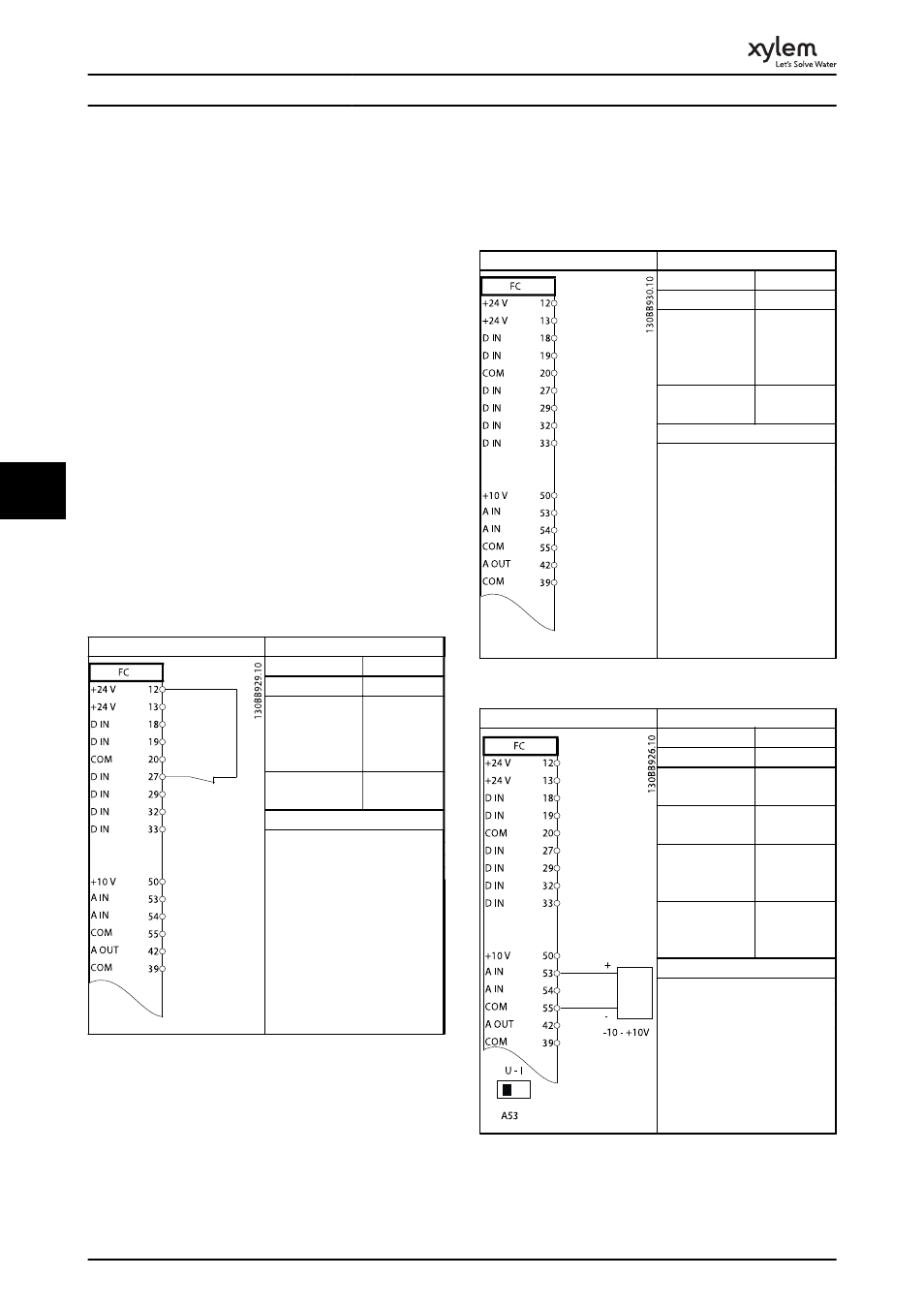
6.2 Application
Examples
Parameters
Function
Setting
1-29 Automatic
Motor
Adaptation
(AMA)
[1] Enable
complete
AMA
5-12 Terminal 27
Digital Input
[2]* Coast
inverse
* = Default Value
Notes/comments: Parameter
group 1-2* must be set
according to motor.
Table 6.1 AMA with T27 Connected
Parameters
Function
Setting
1-29 Automatic
Motor
Adaptation
(AMA)
[1] Enable
complete
AMA
5-12 Terminal 27
Digital Input
[0] No
operation
* = Default Value
Notes/comments:
Parameter group 1-2* must be
set according to motor.
Table 6.2 AMA without T27 Connected
Parameters
Function
Setting
6-10 Terminal 53
Low Voltage
0.07 V*
6-11 Terminal 53
High Voltage
10 V*
6-14 Terminal 53
Low Ref./Feedb.
Value
0 Hz
6-15 Terminal 53
High Ref./Feedb.
Value
50 Hz
* = Default Value
Notes/comments:.
Table 6.3 Analog Speed Reference (Voltage)
Application Set-Up Examples
44
6
6