Bell & Gossett P2001487 Technologic Pump Controller User Manual
Page 60
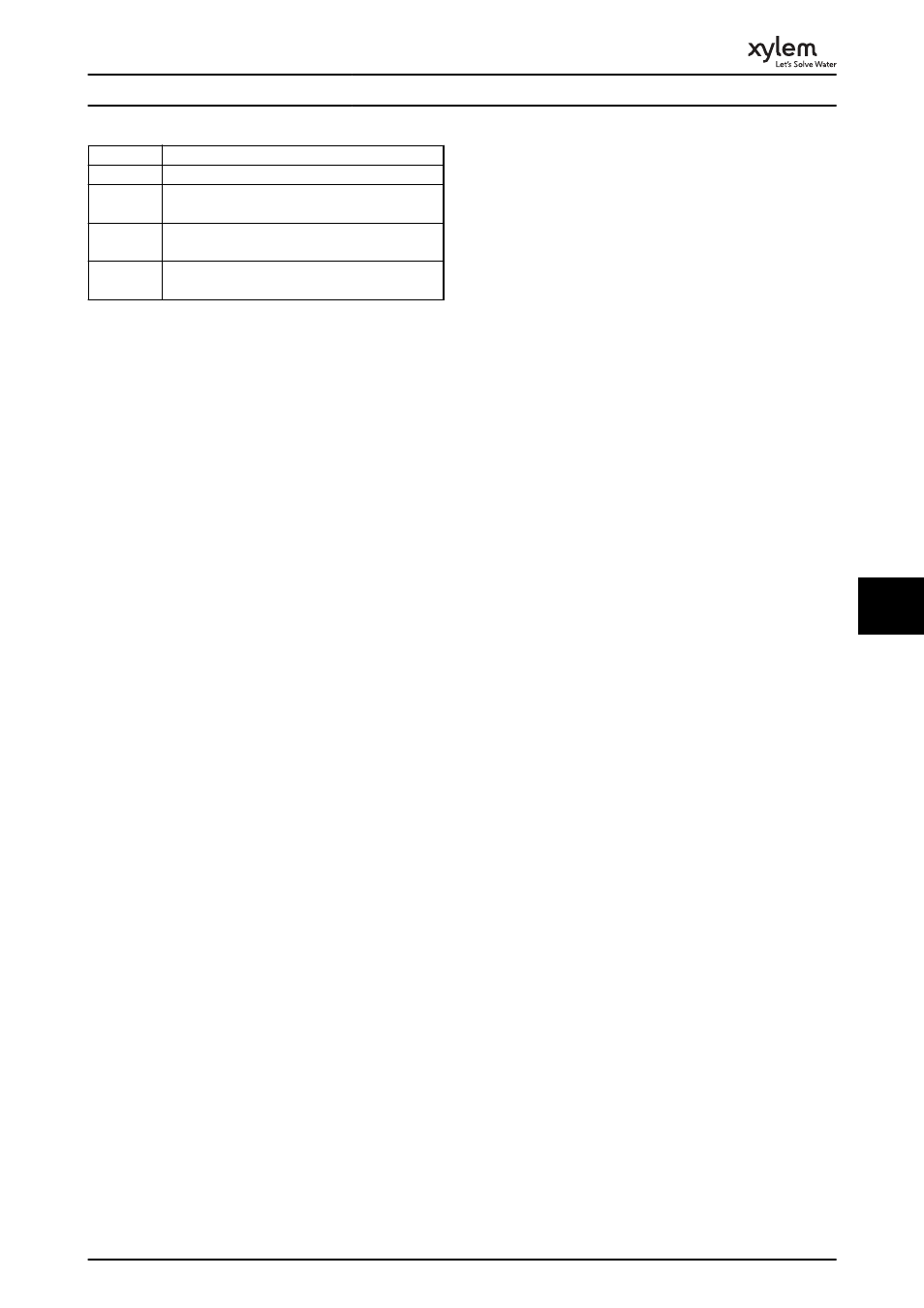
No.
Text
3072-5122
Parameter value is outside its limits
5123
Option in slot A: Hardware incompatible with
control board hardware
5124
Option in slot B: Hardware incompatible with
control board hardware
5376-6231
Internal fault. Contact your Xylem supplier or
Xylem Service Department.
Table 8.2 Internal Fault Codes
ALARM 39, Heatsink sensor
No feedback from the heatsink temperature sensor.
The signal from the IGBT thermal sensor is not available on
the power card. The problem could be on the power card,
on the gate drive card, or the ribbon cable between the
power card and gate drive card.
WARNING 40, Overload of digital output terminal 27
Check the load connected to terminal 27 or remove short-
circuit connection. Check 5-00 Digital I/O Mode and
5-01 Terminal 27 Mode.
WARNING 41, Overload of digital output terminal 29
Check the load connected to terminal 29 or remove short-
circuit connection. Check 5-00 Digital I/O Mode and
5-02 Terminal 29 Mode.
WARNING 42, Overload of digital output on X30/6 or
overload of digital output on X30/7
For X30/6, check the load connected to X30/6 or remove
the short-circuit connection. Check 5-32 Term X30/6 Digi
Out (MCB 101).
For X30/7, check the load connected to X30/7 or remove
the short-circuit connection. Check 5-33 Term X30/7 Digi
Out (MCB 101).
ALARM 45, Earth fault 2
Earth (ground) fault on start-up.
Troubleshooting
Check for proper earthing (grounding) and loose
connections.
Check for proper wire size.
Check motor cables for short-circuits or leakage
currents.
ALARM 46, Power card supply
The supply on the power card is out of range.
There are three power supplies generated by the switch
mode power supply (SMPS) on the power card: 24 V, 5 V,
±18 V. When powered with 24 V DC with the MCB 107
option, only the 24 V and 5 V supplies are monitored.
When powered with three phase mains voltage, all three
supplies are monitored.
Troubleshooting
Check for a defective power card.
Check for a defective control card.
Check for a defective option card.
If a 24 V DC power supply is used, verify proper
supply power.
WARNING 47, 24 V supply low
The 24 V DC is measured on the control card. The external
24 V DC backup power supply may be overloaded,
otherwise contact the Xylem supplier.
WARNING 48, 1.8 V supply low
The 1.8 V DC supply used on the control card is outside of
allowable limits. The power supply is measured on the
control card. Check for a defective control card. If an
option card is present, check for an overvoltage condition.
WARNING 49, Speed limit
When the speed is not within the specified range in
4-11 Motor Speed Low Limit [RPM] and 4-13 Motor Speed
High Limit [RPM], the frequency converter shows a warning.
When the speed is below the specified limit in 1-86 Trip
Speed Low [RPM] (except when starting or stopping) the
frequency converter will trip.
ALARM 50, AMA calibration failed
Contact your Xylem supplier or Xylem Service Department.
ALARM 51, AMA check U
nom
and I
nom
The settings for motor voltage, motor current and motor
power are wrong. Check the settings in parameters 1-20 to
1-25.
ALARM 52, AMA low I
nom
The motor current is too low. Check the settings.
ALARM 53, AMA motor too big
The motor is too big for the AMA to operate.
ALARM 54, AMA motor too small
The motor is too small for the AMA to operate.
ALARM 55, AMA parameter out of range
The parameter values of the motor are outside of the
acceptable range. AMA will not run.
ALARM 56, AMA interrupted by user
The user has interrupted the AMA.
ALARM 57, AMA internal fault
Try to restart AMA again. Repeated restarts can over heat
the motor.
ALARM 58, AMA Internal fault
Contact your Xylem supplier.
WARNING 59, Current limit
The current is higher than the value in 4-18 Current Limit.
Ensure that Motor data in parameters 1-20 to 1-25 are set
correctly. Possibly increase the current limit. Be sure that
the system can operate safely at a higher limit.
WARNING 60, External interlock
A digital input signal is indicating a fault condition external
to the frequency converter. An external interlock has
commanded the frequency converter to trip. Clear the
Warnings and Alarms
57
8
8