7 status messages, 1 status display, 2 status message definitions – Bell & Gossett P2001487 Technologic Pump Controller User Manual
Page 51
7 Status Messages
7.1 Status
Display
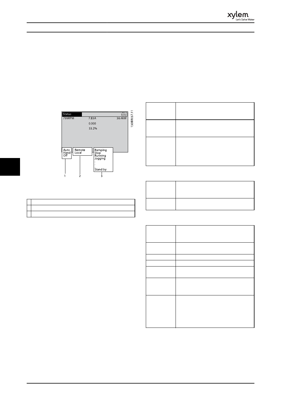
When the frequency converter is in status mode, status
messages are generated automatically and appear in the
bottom line of the display (see Illustration 7.1.)
Illustration 7.1 Status Display
1 Operation Mode (see Table 7.2)
2 Reference Site (see Table 7.3)
3 Operation Status (see Table 7.4)
Table 7.1 Legend to Illustration 7.1
7.2 Status Message Definitions
Table 7.2 to Table 7.4 define the meaning of the displayed
status messages.
Off
The frequency converter does not react to any
control signal until [Auto On] or [Hand On] is
pressed.
Auto On
The frequency converter is controlled from the
control terminals and/or the serial communi-
cation.
Hand On
The frequency converter can be controlled by
the navigation keys on the LCP. Stop
commands, reset, reversing, DC brake, and
other signals applied to the control terminals
can override local control.
Table 7.2 Operation Mode
Remote
The speed reference is given from external
signals, serial communication, or internal
preset references.
Local
The frequency converter uses [Hand On]
control or reference values from the LCP.
Table 7.3 Reference Site
AC Brake
AC Brake was selected in 2-10 Brake Function.
The AC brake over-magnetizes the motor to
achieve a controlled slow down.
AMA finish OK
Automatic motor adaptation (AMA) was
carried out successfully.
AMA ready
AMA is ready to start. Press [Hand On] to start.
AMA running
AMA process is in progress.
Braking
The brake chopper is in operation. Generative
energy is absorbed by the brake resistor.
Braking max.
The brake chopper is in operation. The power
limit for the brake resistor defined in
2-12 Brake Power Limit (kW) has been reached.
Coast
•
Coast inverse was selected as a function
for a digital input (parameter group 5-1*
Digital Inputs). The corresponding terminal
is not connected.
•
Coast activated by serial communication
Status Messages
48
7
7