7 terminal 53 and 54 switches, 6 serial communication, Warning – Bell & Gossett P2001487 Technologic Pump Controller User Manual
Page 23
applications, the user wires an external interlock
device to terminal 27
•
When no interlock device is used, wire a jumper
between control terminal 12 (recommended) or
13 to terminal 27. This provides in internal 24 V
signal on terminal 27
•
No signal present prevents the unit from
operating
•
When the status line at the bottom of the LCP
reads AUTO REMOTE COASTING or Alarm 60
External Interlock is displayed, this indicates that
the unit is ready to operate but is missing an
input signal on terminal 27.
•
When factory installed optional equipment is
wired to terminal 27, do not remove that wiring.
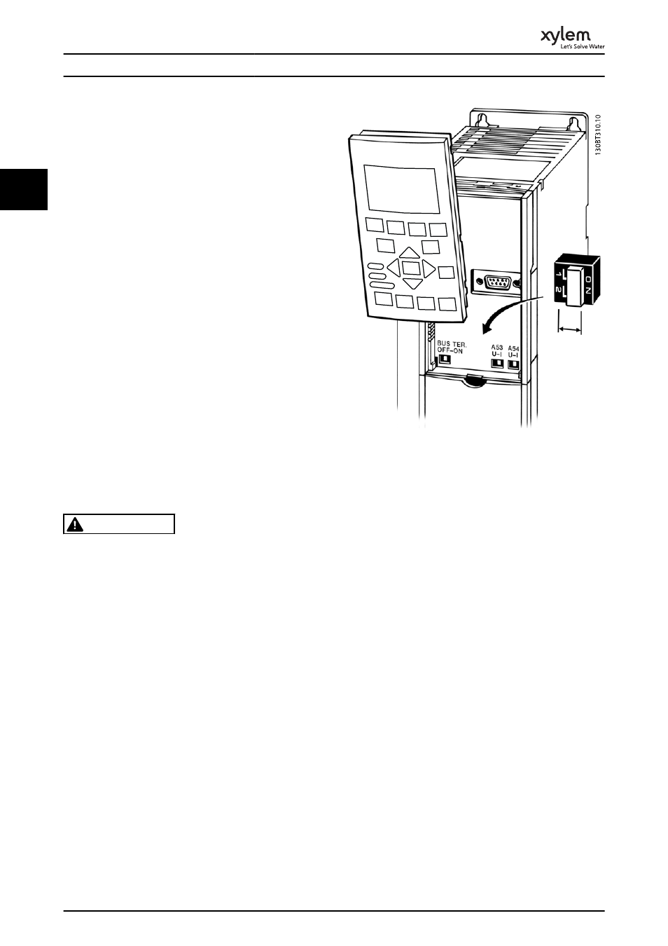
2.4.5.7 Terminal 53 and 54 Switches
•
Analog input terminals 53 and 54 can select
either voltage (0 to 10 V) or current (0/4-20 mA)
input signals
•
Remove power to the frequency converter before
changing switch positions
•
Set switches A53 and A54 to select the signal
type. U selects voltage, I selects current.
•
The switches are accessible when the LCP has
been removed (see Illustration 2.26).
WARNING
Some option cards available for the unit may cover these
switches and must be removed to change switch
settings. Always remove power to the unit before
removing option cards.
•
Terminal 53 default is for a speed reference signal
in open loop set in 16-61 Terminal 53 Switch
Setting
•
Terminal 54 default is for a feedback signal in
closed loop set in 16-63 Terminal 54 Switch Setting
Illustration 2.26 Location of Terminals 53 and 54 Switches
2.4.6 Serial Communication
RS-485 is a two-wire bus interface compatible with multi-
drop network topology, i.e. nodes can be connected as a
bus, or via drop cables from a common trunk line. A total
of 32 nodes can be connected to one network segment.
Repeaters divide network segments. Note that each
repeater functions as a node within the segment in which
it is installed. Each node connected within a given network
must have a unique node address, across all segments.
Terminate each segment at both ends, using either the
termination switch (S801) of the frequency converters or a
biased termination resistor network. Always use screened
twisted pair (STP) cable for bus cabling, and always follow
good common installation practice.
Low-impedance earth (ground) connection of the screen at
every node is important, including at high frequencies.
Thus, connect a large surface of the screen to earth
(ground), for example with a cable clamp or a conductive
cable gland. It may be necessary to apply potential-
equalizing cables to maintain the same earth (ground)
potential throughout the network. Particularly in instal-
lations with long cables.
To prevent impedance mismatch, always use the same
type of cable throughout the entire network. When
connecting a motor to the frequency converter, always use
screened motor cable.
Installation
20
2
2