2 lifting, 3 mounting, 4 tightening torques – Bell & Gossett P2001487 Technologic Pump Controller User Manual
Page 12
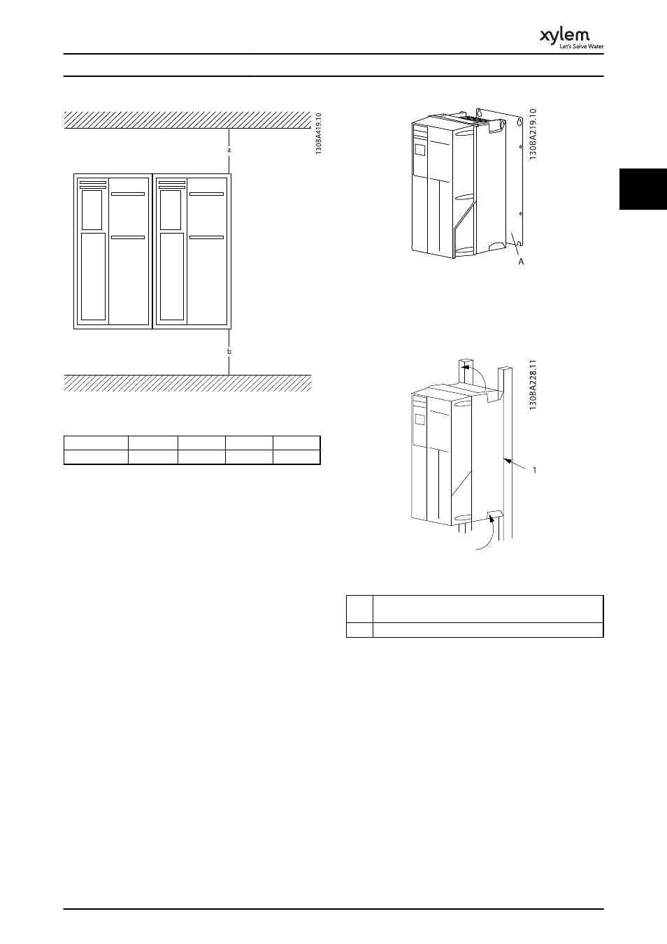
Illustration 2.1 Top and Bottom Cooling Clearance
Enclosure
A2-A5
B1-B4
C1, C3
C2, C4
a/b [mm]
100
200
200
225
Table 2.1 Minimum Airflow Clearance Requirements
2.3.2 Lifting
•
Check the weight of the unit to determine a safe
lifting method
•
Ensure that the lifting device is suitable for the
task
•
If necessary, plan for a hoist, crane, or forklift with
the appropriate rating to move the unit
•
For lifting, use hoist rings on the unit, when
provided
2.3.3 Mounting
•
Mount the unit vertically
•
The frequency converter allows side by side
installation
•
Ensure that the strength of the mounting location
will support the unit weight
•
Mount the unit to a solid flat surface or to the
optional back plate to provide cooling airflow
(see Illustration 2.2 and Illustration 2.3)
•
Improper mounting can result in over heating
and reduced performance
•
Use the slotted mounting holes on the unit for
wall mounting, when provided
Illustration 2.2 Proper Mounting with Back Plate
Item A in Illustration 2.2 and Illustration 2.3 is a back plate
properly installed for required airflow to cool the unit.
Illustration 2.3 Proper Mounting with Railings
Item
#
Description
1
Back plate
Table 2.2 Legend to Illustration 2.3
NOTE
Back plate is needed when mounted on railings.
2.3.4 Tightening Torques
See 10.4 Connection Tightening Torques for proper
tightening specifications.
Installation
9
2
2