8 warnings and alarms, 1 system monitoring, 2 warning and alarm types – Bell & Gossett P2001487 Technologic Pump Controller User Manual
Page 54: 3 warning and alarm definitions
8 Warnings and Alarms
8.1 System
Monitoring
The frequency converter monitors the condition of its
input power, output, and motor factors as well as other
system performance indicators. A warning or alarm may
not necessarily indicate a problem internal to the
frequency converter itself. In many cases, it indicates failure
conditions from input voltage, motor load or temperature,
external signals, or other areas monitored by the frequency
converter’s internal logic. Be sure to investigate those areas
exterior to the frequency converter as indicated in the
alarm or warning.
8.2 Warning and Alarm Types
Warnings
A warning is issued when an alarm condition is impending
or when an abnormal operating condition is present and
may result in the frequency converter issuing an alarm. A
warning clears by itself when the abnormal condition is
removed.
Alarms
Trip
An alarm is issued when the frequency converter is
tripped, that is, the frequency converter suspends
operation to prevent frequency converter or system
damage. The motor will coast to a stop. The frequency
converter logic will continue to operate and monitor the
frequency converter status. After the fault condition is
remedied, the frequency converter can be reset. It will
then be ready to start operation again.
A trip can be reset in any of 4 ways
•
Press [Reset] on the LCP
•
Digital reset input command
•
Serial communication reset input command
•
Auto reset
An alarm that causes the frequency converter to trip-lock
requires that input power is cycled. The motor will coast to
a stop. The frequency converter logic will continue to
operate and monitor the frequency converter status.
Remove input power to the frequency converter and
correct the cause of the fault, then restore power. This
action puts the frequency converter into a trip condition as
described above and may be reset in any of those 4 ways.
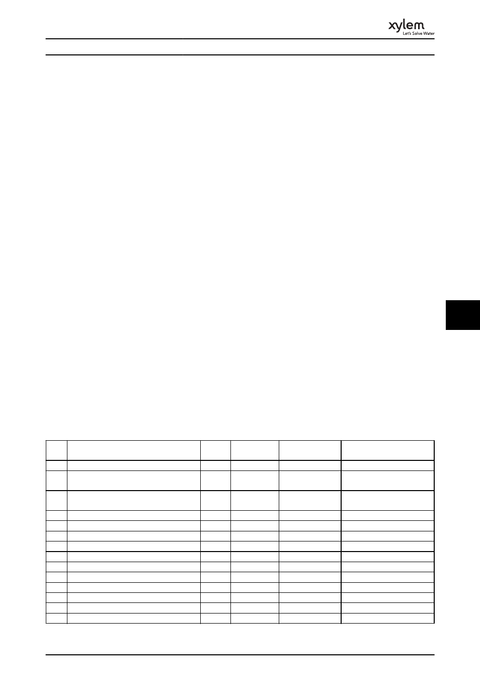
8.3 Warning and Alarm Definitions
Table 8.1 defines whether a warning is issued before an alarm, and whether the alarm trips the unit or trip locks the unit.
No.
Description
Warnin
g
Alarm/Trip
Alarm/Trip Lock
Parameter Reference
1
10 Volts low
X
2
Live zero error
(X)
(X)
6-01 Live Zero Timeout
Function
4
Mains phase loss
(X)
(X)
(X)
14-12 Function at Mains
Imbalance
5
DC link voltage high
X
6
DC link voltage low
X
7
DC over voltage
X
X
8
DC under voltage
X
X
9
Inverter overloaded
X
X
10
Motor ETR over temperature
(X)
(X)
1-90 Motor Thermal Protection
11
Motor thermistor over temperature
(X)
(X)
1-90 Motor Thermal Protection
12
Torque limit
X
X
13
Over Current
X
X
X
14
Earth (Ground) fault
X
X
X
15
Hardware mismatch
X
X
Warnings and Alarms
51
8
8