4 ac mains connection, 5 control wiring – Bell & Gossett P2001487 Technologic Pump Controller User Manual
Page 19
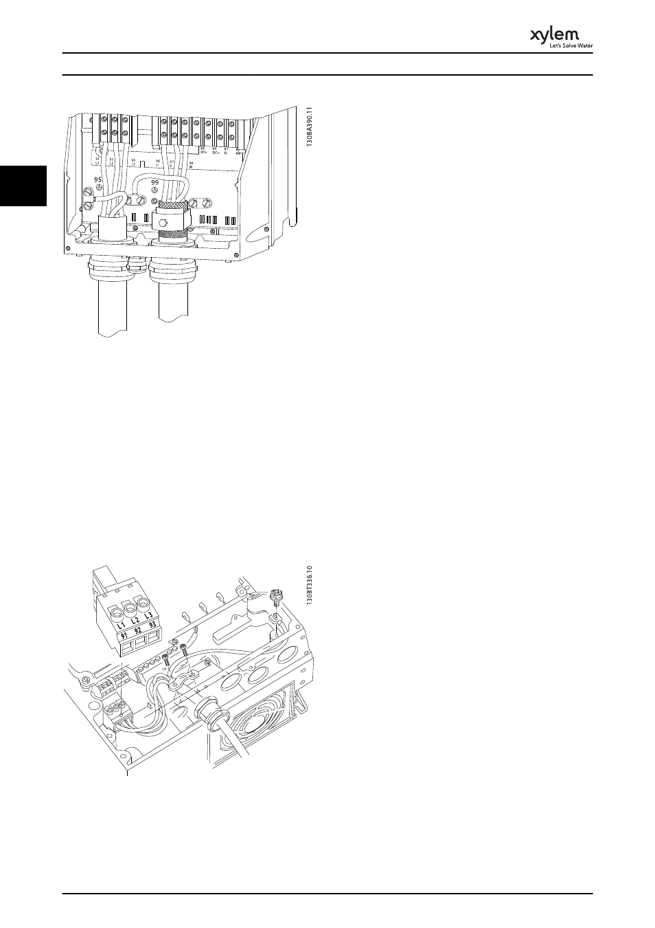
Illustration 2.15 Motor Connection for C1 and C2
2.4.4 AC Mains Connection
•
Size wiring based upon the input current of the
frequency converter. For maximum wire sizes see
10.1 Power-dependent Specifications.
•
Comply with local and national electrical codes
for cable sizes.
•
Connect 3-phase AC input power wiring to
terminals L1, L2, and L3 (see Illustration 2.16).
•
Depending on the configuration of the
equipment, input power will be connected to the
mains input terminals or the input disconnect.
Illustration 2.16 Connecting to AC Mains
•
Ground the cable in accordance with grounding
instructions provided in 2.4.2 Earth (Grounding)
Requirements
•
All frequency converters may be used with an
isolated input source as well as with ground
reference power lines. When supplied from an
isolated mains source (IT mains or floating delta)
or TT/TN-S mains with a grounded leg (grounded
delta), set 14-50 RFI Filter to OFF. When off, the
internal RFI filtercapacitors between the chassis
and the intermediate circuit are isolated to avoid
damage to the intermediate circuit and to reduce
earth capacity currents in accordance with IEC
61800-3.
The electronic thermal relay in the frequency converter has
received UL-approval for single motor protection, when
1-90 Motor Thermal Protectionis set for ETR Trip and
1-24 Motor Current is set to the rated motor current (see
motor name plate).
For thermal motor protection it is also possible to use the
MCB 112 PTC Thermistor Card option. This card provides
ATEX certificate to protect motors in explosion hazardous
areas, Zone 1/21 and Zone 2/22. When 1-90 Motor Thermal
Protection is set to [20] ATEX ETR is combined with the use
of MCB 112, it is possible to control an Ex-e motor in
explosion hazardous areas. Consult the programming
guide for details on how to set up the frequency converter
for safe operation of Ex-e motors.
2.4.5 Control Wiring
•
Isolate control wiring from high power
components in the frequency converter.
•
If the frequency converter is connected to a
thermistor, for PELV isolation, optional thermistor
control wiring must be reinforced/double
insulated. A 24 V DC supply voltage is
recommended.
Installation
16
2
2