Bell & Gossett P2001487 Technologic Pump Controller User Manual
Page 78
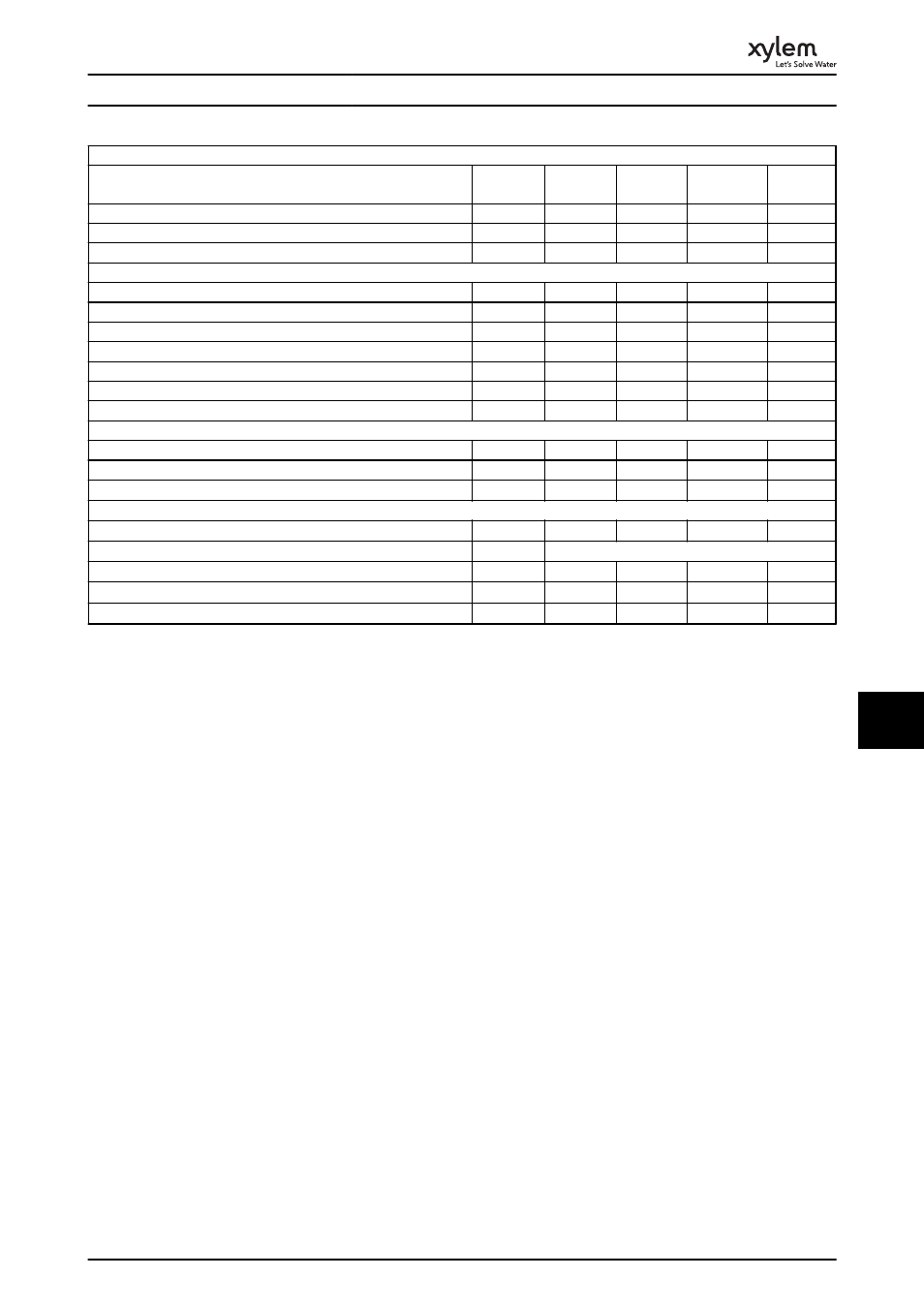
Normal overload 110% for 1 minute
Frequency converter
Typical Shaft Output [kW]
P30K
37
P37K
45
P45K
55
P55K
75
P75K
90
Typical Shaft Output [HP] at 575 V
40
50
60
75
100
IP21/NEMA 1
C2
C2
C2
C2
C2
IP55/NEMA 12
C2
C2
C2
C2
C2
Output current
Continuous (3 x 525-550 V) [A]
43
54
65
87
105
Intermittent (3 x 525-550 V) [A]
47.3
59.4
71.5
95.7
115.5
Continuous (3 x 551-690 V) [A]
41
52
62
83
100
Intermittent (3 x 551-690 V) [A]
45.1
57.2
68.2
91.3
110
Continuous kVA (550 V AC) [kVA]
41
51.4
61.9
82.9
100
Continuous kVA (575 V AC) [kVA]
40.8
51.8
61.7
82.7
99.6
Continuous kVA (690 V AC) [kVA]
49
62.1
74.1
99.2
119.5
Max. input current
Continuous (3 x 525-690 V) [A]
49
59
71
87
99
Intermittent (3 x 525-690 V) [A]
53.9
64.9
78.1
95.7
108.9
Max. pre-fuses
1)
[A]
100
125
160
160
160
Additional specifications
Estimated power loss at rated max. load [W]
4)
592
720
880
1200
1440
Max. cable size (mains, motor, brake) [mm
2
]/(AWG)
2)
[95]/(4/0)
Weight IP21 [kg]
65
65
65
65
65
Weight IP55 [kg]
65
65
65
65
65
Efficiency
4)
0.98
0.98
0.98
0.98
0.98
Table 10.13 Mains Supply 3 x 525-690 V AC IP21-IP55/NEMA 1-NEMA 12
1)
For type of fuse, see 10.3 Fuse Specifications
2)
American Wire Gauge
3)
Measured using 5 m screened motor cables at rated load and rated frequency
4)
The typical power loss is at normal load conditions and expected to be within
±
15% (tolerance relates to variety in voltage and cable
conditions).
Values are based on a typical motor efficiency (eff2/eff3 border line). Lower efficiency motors will also add to the power loss in the frequency
converter and vice versa.
If the switching frequency is raised from nominal the power losses may rise significantly.
LCP and typical control card power consumptions are included. Further options and customer load may add up to 30 W to the losses. (Though
typically only 4 W extra for a fully loaded control card or options for slot A or slot B, each).
Although measurements are made with state of the art equipment, some measurement inaccuracy must be allowed for (
±
5%).
5)
(A2+A3 may be converted to IP21 using a conversion kit. (See also Mechanical mounting and IP21/Type 1 Enclosure kit in the Design Guide.))
6)
(B3+B4 and C3+C4 may be converted to IP21 using a conversion kit. (See also items Mechanical mounting and IP21/Type 1 Enclosure kit in the
Design Guide.))
Specifications
75
10
10