Ac electrical characteristics, Lm93 – Rainbow Electronics LM93 User Manual
Page 88
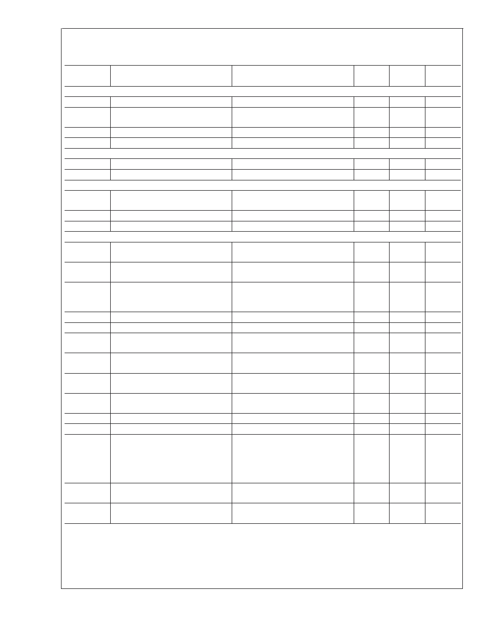
AC Electrical Characteristics
The following limits apply for +3.0 V
DC
to +3.6 V
DC
, unless otherwise noted. Bold face limits apply for T
A
= T
J
= T
MIN
to
T
MAX
of the operating range; all other limits T
A
= T
J
= 25˚C unless otherwire noted.
Symbol
Parameter
Conditions
Typical
Limits
Units
(Limits)
FAN RPM-TO-DIGITAL CHARACTERISTICS
Counter Resolution
14
bits
Number of fan tach pulses count is
based on
2
pulses
Counter Frequency
22.5
kHz
Accuracy
±
6
% (max)
PWM OUTPUT CHARACTERISTICS
Frequency Tolerances
±
6
% (max)
Duty-Cycle Tolerance
±
2
±
6
% (max)
RESET INPUT/OUTPUT CHARACTERISTICS
Output Pulse Width
Upon Power Up
250
330
ms (min)
ms (max)
Minimum Input Pulse Width
10
µs (min)
Reset Output Fall Time
1.6V to 0.4V Logic Levels
1
µs (max)
SMBUS TIMING CHARACTERISTICS
f
SMBCLK
SMBCLK (Clock) Clock Frequency
10
100
kHz (min)
kHz (max)
t
BUF
SMBus Free Time between Stop and
Start Conditions
4.7
µs (min)
t
HD;STA
Hold time after (Repeated) Start
Condition. After this period, the first
clock is generated.
4.0
µs (min)
t
SU;STA
Repeated Start Condition Setup Time
4.7
µs (min)
t
SU;STO
Stop Condition Setup Time
4.0
µs (min)
t
SU;DAT
Data Input Setup Time to SMBCLK
High
250
ns (min)
t
HD;DAT
Data Output Hold Time after SMBCLK
Low
300
930
ns (min)
ns (max)
t
LOW
SMBCLK Low Period
4.7
50
µs (min)
µs (max)
t
HIGH
SMBCLK High Period
4.0
50
µs (min)
µs (max)
t
R
Rise Time
1
µs (max)
t
F
Fall Time
300
ns (max)
t
TIMEOUT
Timeout
SMBDAT or SMBCLK low
time required to
reset the Serial Bus
Interface to the Idle State
31
25
35
ms
ms (min)
ms (max)
t
POR
Time in which a device must be
operational after power-on reset
V
DD
>
+2.8V
500
ms (max)
C
L
Capacitance Load on SMBCLK and
SMBDAT
400
pF (max)
LM93
www.national.com
88