0 using the lm93 – Rainbow Electronics LM93 User Manual
Page 29
15.0 Using The LM93
(Continued)
size and cost of the inductor and other components used in
the output stage. The PWM outputs of the LM93 can operate
up to 22.5 kHz with a step size of 6.25%.
The LM93 fan control method uses a look up table that
contains 12 temperature offset settings and a base tempera-
ture. The actual duty cycle value for each step is pre-
assigned. There are two possible assignments. They are
dependent on the PWM output to Zone binding and the
PWM output frequency. The temperature of each step is
determined by the programmed offsets and zone base tem-
perature. There are two sets of offset values, one set applies
to Zone 1 and Zone 2 while the other set applies to Zone 3
and Zone 4. Each zone has an independent base tempera-
ture. A measured temperature can then be correlated to a
PWM duty cycle level. Programmable temperature hyster-
esis is included that prevents fan speed oscillations between
two steps. Each offset table has one hysteresis value as-
signed to it. Therefore, Zones 1 and 2 share a hysteresis
value while Zones 3 and 4 share a different hysteresis value.
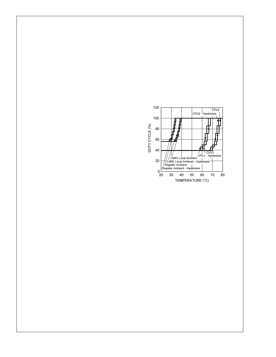
Shown in Figure 1 is a plot of one example of the transfer
function of the PWM output duty cycle (%) with respect to
temperature (˚C) for Zone 1 - 4. Table Zone 1/2 (CPU1 and
CPU2) Table and Table Zone 3/4 (LM93 Ambient and Exter-
nal Ambient) Table show the actual register values used for
the plot. Available for download from the National web site,
at www.national.com/appinfo/tempsensors under design
tools, is an excel spread sheet that allows you to enter the
register values then generate curves similar to the ones
shown in Figure 1 as well as tables similar toTable Zone 1/2
(CPU1 and CPU2) Table and Table Zone 3/4 (LM93 Ambient
and External Ambient) Table. For this example: Zones 1 and
2 are bound to PWM1 and PWM1 is programmed to have a
low frequency PWM signal; Zones 3 and 4 are bound to
PWM2 and PWM2 is programmed to have a high frequency
PWM signal. As can be seen in Table Zone 1/2 (CPU1 and
CPU2) Table and Table Zone 3/4 (LM93 Ambient and Exter-
nal Ambient) Table the duty cycle assignments differ. Low
frequency PWM output assignments have a non-linear incre-
mental increase in the duty cycle as shown in Table Zone 1/2
(CPU1 and CPU2) Table while high frequency PWM assign-
ments have a linear incremental increase in the duty cycle as
shown in Table Zone 3/4 (LM93 Ambient and External Am-
bient) Table.
To minimize the size of the LM93’s lookup table structure,
temperature values in the registers are programmed as an
offset value of 4 bits. This offset gets added in a cumulative
manner to the 8-bit base temperature. The calculated tem-
perature is then used in the comparison that determines the
PWM output duty cycle. The minimum PWM (minPWM)
value sets the duty cycle when the measured temperature is
less than or equal to the base temperature. All offset values
that map to a PWM value less than or equal to the minPWM
setting must be set to zero as shown in Table Zone 1/2
(CPU1 and CPU2) Table and Table Zone 3/4 (LM93 Ambient
and External Ambient) Table. If the offset values are not set
to zero, the LM93 fan control circuitry may function unpre-
dictably.
Duty cycle levels may be skipped by setting their offset value
to zero. As shown in Table Zone 1/2 (CPU1 and CPU2) Table
, the 53.57% duty cycle step is skipped. When the tempera-
ture exceeds 74˚C for CPU1 and 64˚C for CPU2 the duty
cycle changes from 50% to 57.14%.
20068228
FIGURE 1. Example of the LM93 Fan Control Transfer
Function. Download an excel spread sheet from
www.national.com/appinfo/tempsensors that allows
you to enter the fan control register values and then
automatically generate a similar curve.
LM93
www.national.com
29