8 register 47hb_fan error status, 5 host error status registers, 1 register 48hh_error status 1 – Rainbow Electronics LM93 User Manual
Page 45: 8 register 47h, B_fan error status, 1 register 48h, H_error status 1, 0 registers
16.0 Registers
(Continued)
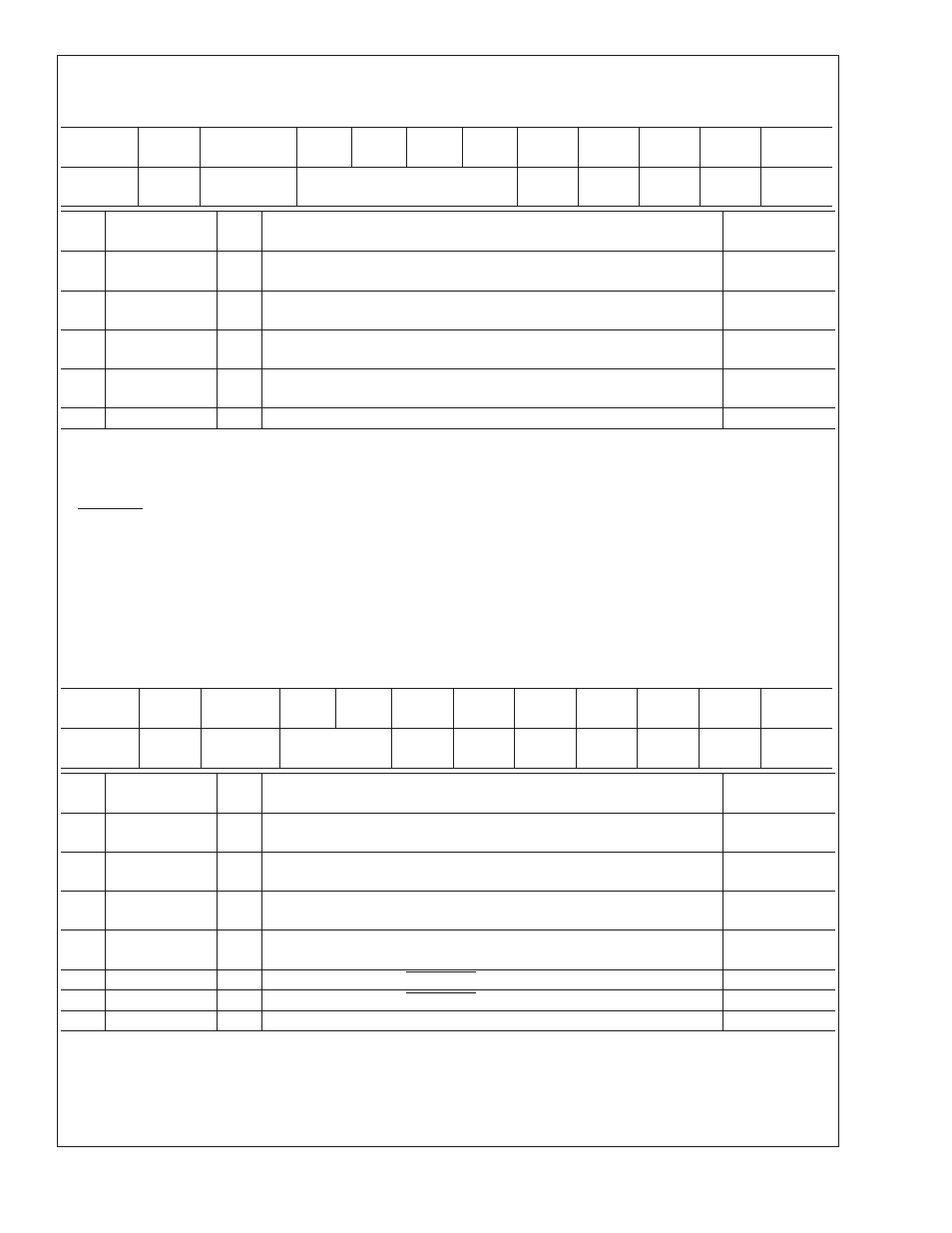
16.4.8 Register 47h
B_Fan Error Status
Register
Address
Read/
Write
Register
Name
Bit 7
Bit 6
Bit 5
Bit 4
Bit 3
Bit 2
Bit 1
Bit 0
Default
Value
47h
RWC
B_Fan
Error Status
RES
FAN4
_ERR
FAN3
_ERR
FAN2
_ERR
FAN1
_ERR
00h
Bit
Name
R/W
Description
Sleep
Masking
0
FAN1_ERR
RWC This bit is set when the Fan Tach 1 value register is above the value set in
the Fan Tach 1 Limit register.
S1*, S3*, S4/5
1
FAN2_ERR
RWC This bit is set when the Fan Tach 2 value register is above the value set in
the Fan Tach 2 Limit register.
S1*, S3*, S4/5
2
FAN3_ERR
RWC This bit is set when the Fan Tach 3 value register is above the value set in
the Fan Tach 3 Limit register.
S1*, S3*, S4/5
3
FAN4_ERR
RWC This bit is set when the Fan Tach 4 value register is above the value set in
the Fan Tach 4 Limit register.
S1*, S3*, S4/5
7:4
RES
R
Reserved
N/A
16.5 HOST ERROR STATUS REGISTERS
The Host Error Status Registers contain several bits that each represent a particular error event that the LM93 can monitor. The
LM93 sets a given bit whenever the corresponding error event occurs. The HOST_ERR bit in the LM93 Status/Control register
also sets if any bit in the Host Error Status registers is set. The exception to this is the fixed threshold error status bits in the
PROCHOT Error Status registers. They have no influence on HOST_ERR.
Once a bit is set in the Host Error Status registers, it is not automatically cleared by the LM93 if the error event goes away. Each
bit must be cleared by software. If software attempts to clear a bit while the error condition still exists, the bit does not clear.
Software must specifically write a 1 to any bits it wishes to clear in the Host Error Status registers (write-one-to-clear).
Each register described in this section has a column labeled Sleep Masking. This column describes which error events are
masked in various sleep states. The sleep state of the system is communicated to the LM93 by writing to the Sleep State Control
register. If a sleep state in this column has a ‘*’ next to it, it denotes that the error event is optionally masked in that sleep mode,
depending on the Sleep State Mask registers.
16.5.1 Register 48h
H_Error Status 1
Register
Address
Read/
Write
Register
Name
Bit 7
Bit 6
Bit 5
Bit 4
Bit 3
Bit 2
Bit 1
Bit 0
Default
Value
48h
RWC
H_Error
Status 1
RES
VRD2
_ERR
VRD1
_ERR
ZN4
_ERR
ZN3
_ERR
ZN2
_ERR
ZN1
_ERR
00h
Bit
Name
R/W
Description
Sleep
Masking
0
ZN1_ERR
RWC This bit is set when the zone 1 temperature has fallen outside the zone 1
temperature limits.
S3*, S4/5*
1
ZN2_ERR
RWC This bit is set when the zone 2 temperature has fallen outside the zone 2
temperature limits.
S3*, S4/5*
2
ZN3_ERR
RWC This bit is set when the zone 3 temperature has fallen outside the zone 3
temperature limits.
none
3
ZN4_ERR
RWC This bit is set when the zone 4 temperature has fallen outside the zone 4
temperature limits.
none
4
VRD1_ERR
RWC This bit is set when the VRD1_HOT input has been asserted.
S3, S4/5
5
VRD2_ERR
RWC This bit is set when the VRD2_HOT input has been asserted.
S3, S4/5
7:6
RES
R
Reserved
N/A
LM93
www.national.com
45