8 setup registers, 1 register bch, 0 registers – Rainbow Electronics LM93 User Manual
Page 62
16.0 Registers
(Continued)
16.8 SETUP REGISTERS
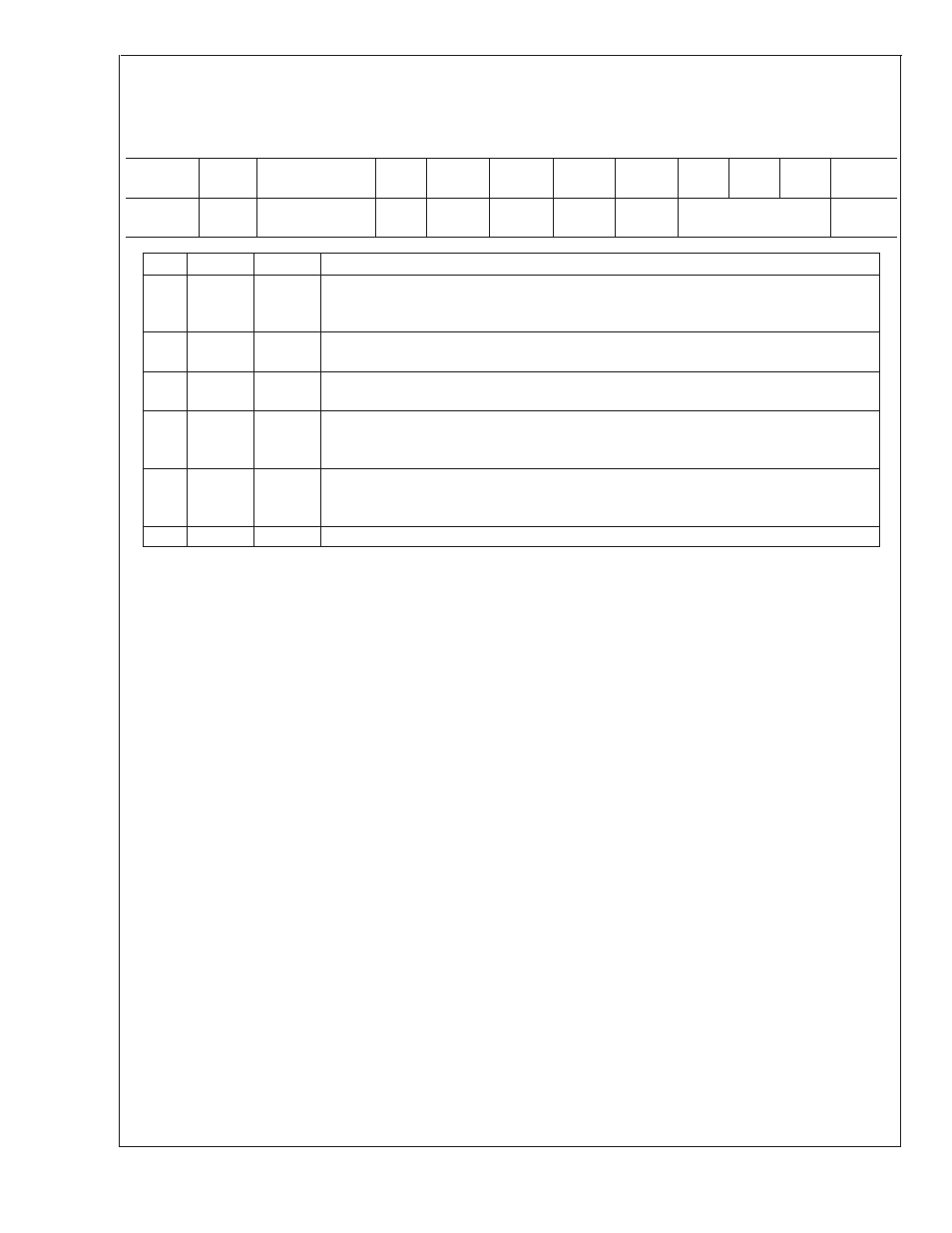
16.8.1 Register BCh
Special Function Control 1 (Voltage Hysteresis and Fan Control Filter Enable)
Register
Address
Read/
Write
Register
Name
Bit 7
Bit 6
Bit 5
Bit 4
Bit 3
Bit 2
Bit 1
Bit 0
Default
Value
BCh
R/W
Special Function
Control 1
RES
FCFE2
FCFE1
LCFE2
LCFE1
VH
00h
Bit
Name
R/W
Description
2:0
VH
R/W
Voltage hysteresis control. This determines the amount of hysteresis to be applied to all
voltage limit comparisons. It applies to both high and low limits. One LSB equals one A/D
count, so the actual voltage represented by one LSB depends on the voltage channel.
3
LCFE1
R/W
Limit Comparison Filter Enable. Setting this bit causes limit comparisons for temperature zone
1 to use the filtered (spike smoothed) temperature instead of the unfiltered temperature.
4
LCFE2
R/W
Limit Comparison Filter Enable. Setting this bit causes limit comparisons for temperature zone
2 to use the filtered (spike smoothed) temperature instead of the unfiltered temperature.
5
FCFE1
R/W
Fan Control Filter Enable. Setting this bit causes fan control functions for zone 1 (including
fan boost) to use the filtered (spike smoothed) temperature instead of the unfiltered
temperature.
6
FCFE2
R/W
Fan Control Filter Enable. Setting this bit causes fan control functions for zone 2 (including
fan boost) to use the filtered (spike smoothed) temperature instead of the unfiltered
temperature.
7
RES
R
Reserved
In order for the LCFE1, LCFE2, FCFE1 and FCFE2 bits to work correctly, the ZN1E and ZN2E bits in the Zones 1/2 Spike
Smoothing Control register should be cleared.
Application Note: If hysteresis for voltage limit comparisons is non-zero, special care needs to be taken when changing the
voltage limit registers while a voltage error condition exists. If software relaxes the voltage limits in an attempt to prevent an error
condition, it may be necessary to relax the limits by an amount greater than the hysteresis value and wait several milliseconds
before attempting to clear the error status bit for the given voltage channel. Once the error status bit has been cleared, the desired
limit(s) can be programmed.
LM93
www.national.com
62