10 prochot monitoring, 11 prochot output control, 10 prochot monitoring 12.11 prochot output control – Rainbow Electronics LM93 User Manual
Page 16: 0 functional description
12.0 Functional Description
(Continued)
mented to a max count for an above temperature trip and
decremented to zero when below the trip temperature set-
ting, to remove the trip.
The minimum time for PROCHOT assertion is time depen-
dant on the FSB frequency. The minimum time that the
processor asserts PROCHOT is estimated to be 187 µs.
12.10 PROCHOT MONITORING
PROCHOT monitoring applies to both the P1_PROCHOT
and P2_PROCHOT inputs. Both inputs are monitored in the
same fashion, but the following description discusses a
single
monitor.
(Px_PROCHOT
represents
both
P1_PROCHOT and P2_PROCHOT).
PROCHOT monitoring is meant to achieve two goals. One
goal is to measure the percentage of time that PROCHOT is
asserted over a programmable time period. The result of this
measurement can be read from an 8-bit register where one
LSB equals 1/256th of the PROCHOT Time Interval (0.39%).
The second goal is to have a status register that indicates,
as a coarse percentage, the amount of time a processor has
been throttled. This second goal is required in order to
communicate information over the NIC using ASF, i.e. status
can be sent, not values.
To achieve the first goal, the PROCHOT input is monitored
over a period of time as defined by the PROCHOT Time
Interval Register. At the end of each time period, the 8-bit
measurement is transferred to the Current Px_PROCHOT
register. Also at the end of each measurement period, the
Current Px_PROCHOT register value is moved to the Aver-
age Px_PROCHOT register by adding the new value to the
old value and dividing the result by 2. Note that the value that
is averaged into the Average Px_PROCHOT register is not
the new measurement but rather the previous measurement.
If the SMBus writes to the Current P1_PROCHOT (or Cur-
rent P2_PROCHOT) register, the capture cycle restarts for
both
monitoring
channels
(P1_PROCHOT
and
P2_PROCHOT). Also note, that a strict average of two 8-bit
values may result in Average Px_PROCHOT reflecting a
value that is one LSB lower than the Current Px_PROCHOT
in steady state.
It should be noted that the 8-bit result has a positive bias of
one half of an LSB. This is necessary because a value of 00h
represents that Px_PROCHOT was not asserted at all dur-
ing the sampling window. Any amount of throttling results in
a reading of 01h.
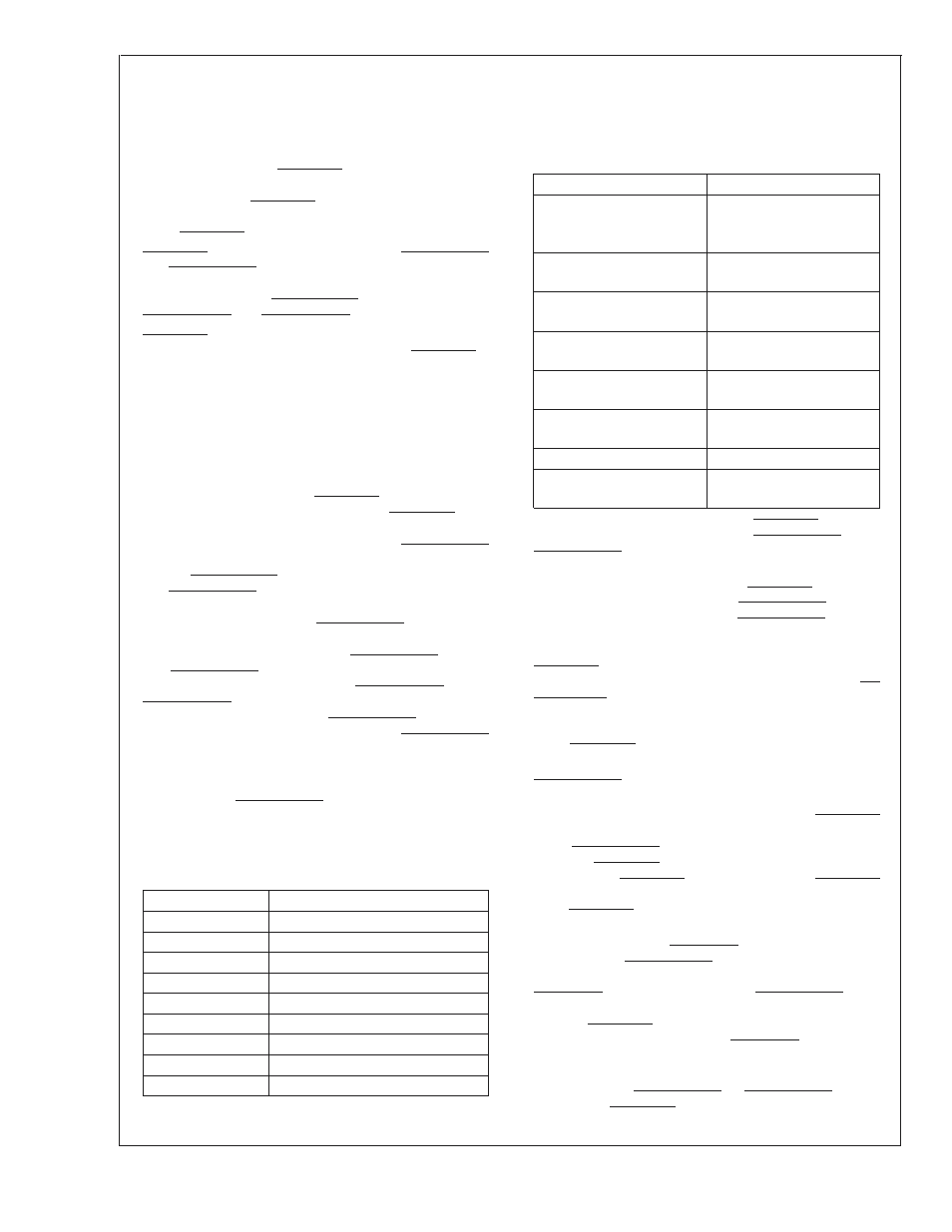
The following table demonstrates the mapping for the 8-bit
result:
8–Bit Result
Percentage Thottled
0
Exactly 0%
1
Between 0% and 0.39%
2
Between 0.39% and 0.78%
A
A
n
Between (n-1)/256 and n/256
A
A
253
Between 98.4% and 98.8%
254
Between 98.8% and 99.2%
255
Greater than 99.2%
To achieve the second goal, the LM93 has several compara-
tors that compare the measured percentage reading against
several fixed and 1 variable value. The variable value is user
programmable.
The result of these comparisons generates several error
status bits described in the following table:
Status Description
Comparison Formula
100% Throttle
PROCHOT was never
de-asserted during
monitoring interval.
Greater than or equal to
75% and less than 100%
193
≤ measured value and
not 100%
Greater than or equal to
50% and less than 75%
129
≤ measured value
<
193
Greater than or equal to
25% and less than 50%
65
≤ measured value
<
129
Greater than or equal to
12.5% and less than 25%
33
≤ measured value
<
65
Greater than 0% and less
than 12.5%
0
<
measured value
<
33
Greater than 0%
0
<
measured value
Greater than user limit
user limit
<
measured
value
These status bits are reflected in the PROCHOT Error Sta-
tus
Registers.
Each
of
the
P1_PROCHOT
and
P2_PROCHOT inputs is monitored independently, and each
has its own set of status registers.
In S3 and S4/5 sleep states, the PROCHOT Monitoring
function does not run. The Current Px_PROCHOT registers
are reset to 00h and the Average Px_PROCHOT registers
hold their current state. Once the sleep state changes back
to S0, the monitoring function is restarted. After the first
PROCHOT measurement has been made, the measure-
ment is written directly into the Current and Average Px-
_PROCHOT registers without performing any averaging. Av-
eraging returns to normal on the second measurement.
12.11 PROCHOT OUTPUT CONTROL
In some cases, it is necessary for the LM93 to drive the
Px_PROCHOT outputs low. There are several conditions
that cause this to happen.
The LM93 can be told to logically short the two PROCHOT
inputs together. When this is done, the LM93 monitors each
of the Px_PROCHOT inputs. If any external device asserts
one of the PROCHOT signals, the LM93 responds by assert-
ing the other PROCHOT signal until the first PROCHOT
signal is de-asserted. This feature should never be enabled
if the PROCHOT signals are already being shorted by an-
other means.
Whenever one of the VRDx_HOT inputs is asserted, the
corresponding Px_PROCHOT pins are asserted by the
LM93. The response time is less than 10 µs. When the
VRDx_HOT input is de-asserted, the Px_PROCHOT pin is
no longer asserted by the LM93. If the LM93 is configured to
short the PROCHOT signals together, it always asserts them
together whenever either of the VRDx_HOT inputs is as-
serted.
Software can manually program the LM93 to drive a PWM
type signal onto P1_PROCHOT or P2_PROCHOT. This is
done via the PROCHOT Override register. See the descrip-
tion of this register for more details. Once again, if the LM93
LM93
www.national.com
16