15 register cahpwm1 control 3, 16 register cbhspecial function pwm1 control 4, 15 register cah – Rainbow Electronics LM93 User Manual
Page 72: Pwm1 control 3, 16 register cbh, Special function pwm1 control 4, 0 registers
16.0 Registers
(Continued)
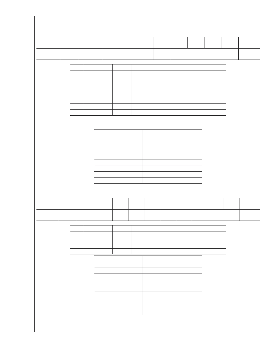
16.8.15 Register CAh
PWM1 Control 3
Register
Address
Read/
Write
Register
Name
Bit 7
Bit 6
Bit 5
Bit 4
Bit 3
Bit 2
Bit 1
Bit 0
Default
Value
CAh
R/W
PWM1
Control 3
SU_DUR
RES
SU_DC
00h
Bit
Name
R/W
Description
3:0
SU_DC
R/W
This field sets the duty cycle that will be used
whenever PWM1 experiences a Spin-Up cycle. This
field accepts 16 possible values that are mapped to
duty cycles according the table in the Auto-Fan
Control section. Setting this field to 0h will effectively
disable Spin-Up.
4
RES
R
Reserved
7:5
SU_DUR
R/W
Sets the Spin-Up duration for PWM1.
Bits 7:5 configure the spin-up duration. When the duty cycle of PWM1 changes from zero to a non-zero value, the spin-up
sequence is activated for the specified amount of time. The available settings are defined according to this table:
SU_DUR
Spin-Up Time
0h
Spin-up disabled
1h
100 ms
2h
250 ms
3h
400 ms
4h
700 ms
5h
1000 ms
6h
2000 ms
7h
4000 ms
16.8.16 Register CBh
Special Function PWM1 Control 4
Register
Address
Read/
Write
Register
Name
Bit 7
Bit 6
Bit 5
Bit 4
Bit 3
Bit 2
Bit 1
Bit 0
Default
Value
CBh
R/W
Special Function
PWM1 Control 4
RES
RES
RES
RES
RES
FREQ1
00h
Bit
Name
R/W
Description
2:0
FREQ1
R/W
PWM1 frequency control. Setting this value controls
the frequency of the PWM1 output according to the
table below.
7:3
RES
R
Reserved
FREQ1 or FREQ2
Frequency of PWM1
or PWM2 (Hz)
0h
22500
1h
96
2h
84
3h
72
4h
60
5h
48
6h
36
7h
12
LM93
www.national.com
72