17 register cchpwm2 control 1, 17 register cch, Pwm2 control 1 – Rainbow Electronics LM93 User Manual
Page 73: 0 registers
16.0 Registers
(Continued)
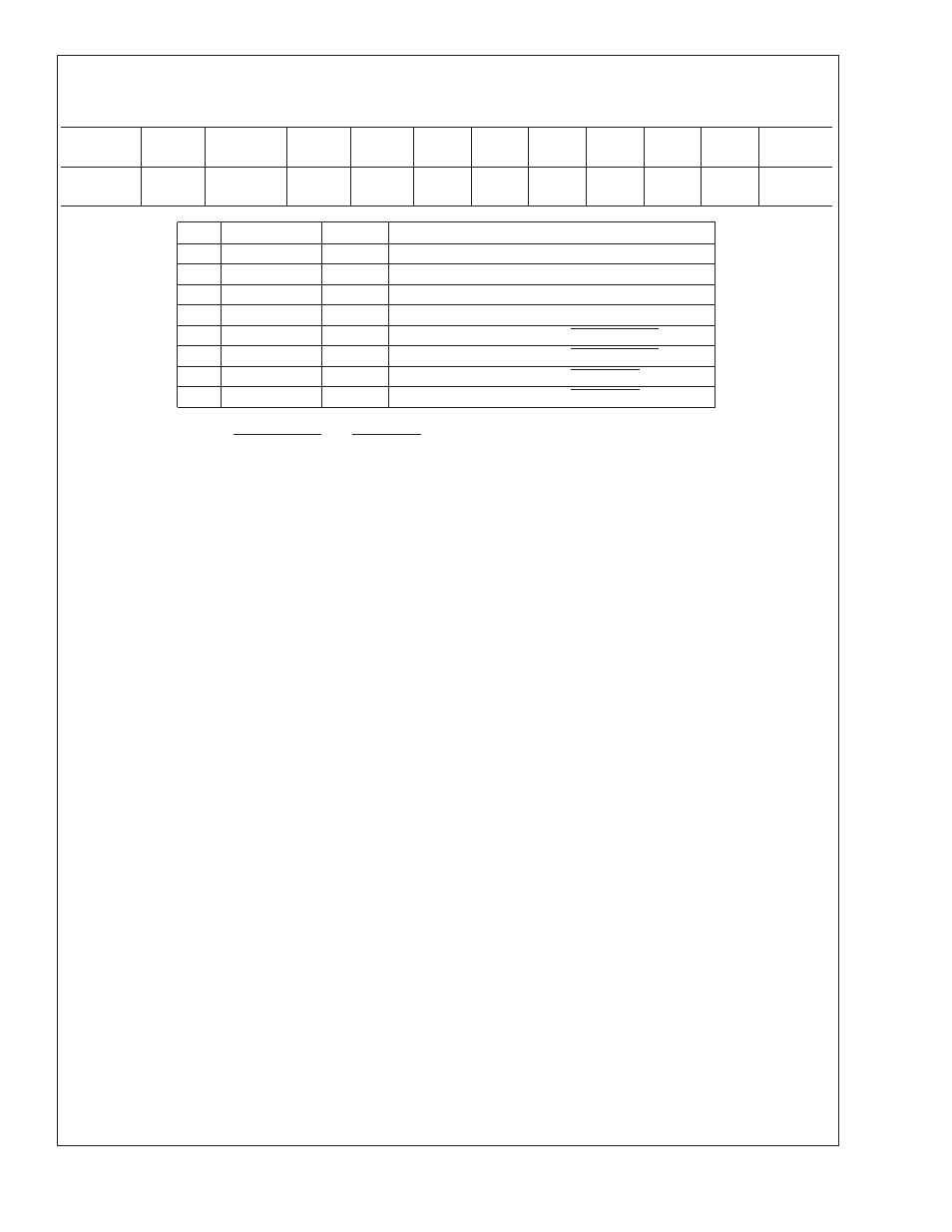
16.8.17 Register CCh
PWM2 Control 1
Register
Address
Read/
Write
Register
Name
Bit 7
Bit 6
Bit 5
Bit 4
Bit 3
Bit 2
Bit 1
Bit 0
Default
Value
CCh
R/W
PWM2
Control 1
VRD2
VRD1
PH2
PH1
ZN4
ZN3
ZN2
ZN1
0Fh
Bit
Name
R/W
Description
0
ZN1
R/W
If set, PWM2 will be bound to temperature zone 1.
1
ZN2
R/W
If set, PWM2 will be bound to temperature zone 2.
2
ZN3
R/W
If set, PWM2 will be bound to temperature zone 3.
3
ZN4
R/W
If set, PWM2 will be bound to temperature zone 4.
4
PH1
R/W
If set, PWM2 will be bound to P1_PROCHOT.
5
PH2
R/W
If set, PWM2 will be bound to P2_PROCHOT.
6
VRD1
R/W
If set, PWM2 will be bound to VRD1_HOT.
7
VRD2
R/W
If set, PWM2 will be bound to VRD2_HOT.
This register can bind PWM2 to several different control sources. The temperature zones control the PWM duty cycle using the
table lookup function. The Px_PROCHOT and VRDx_HOT inputs control the PWM using the ramp up/ramp down functions. If
multiple control sources are bound to PWM2, the largest duty cycle being requested will be used.
LM93
www.national.com
73