2 register 41hb_error status 2, 3 register 42hb_error status 3, 2 register 41h – Rainbow Electronics LM93 User Manual
Page 42: B_error status 2, 3 register 42h, B_error status 3, 0 registers
16.0 Registers
(Continued)
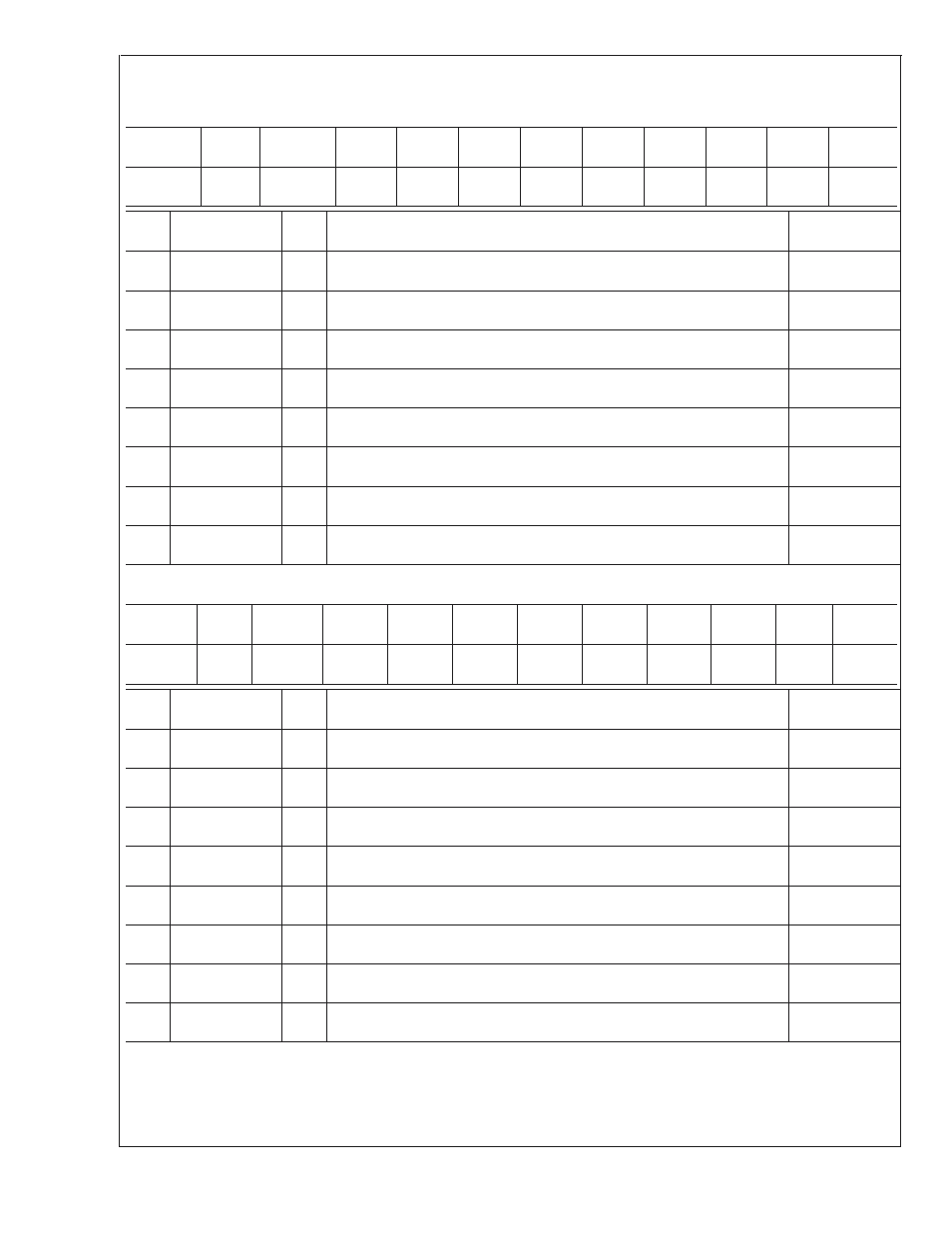
16.4.2 Register 41h
B_Error Status 2
Register
Address
Read/
Write
Register
Name
Bit 7
Bit 6
Bit 5
Bit 4
Bit 3
Bit 2
Bit 1
Bit 0
Default
Value
41h
RWC
B_Error
Status 2
ADIN8
_ERR
ADIN7
_ERR
ADIN6
_ERR
ADIN5
_ERR
ADIN4
_ERR
ADIN3
_ERR
ADIN2
_ERR
ADIN1
_ERR
00h
Bit
Name
R/W
Description
Sleep
Masking
0
AD1_ERR
RWC This bit is set when the AD_IN1 voltage has fallen outside the range defined
by the AD_IN1 Low Limit and the AD_IN1 High Limit registers.
S3, S4/5
1
AD2_ERR
RWC This bit is set when the AD_IN2 voltage has fallen outside the range defined
by the AD_IN2 Low Limit and the AD_IN2 High Limit registers.
S3, S4/5
2
AD3_ERR
RWC This bit is set when the AD_IN3 voltage has fallen outside the range defined
by the AD_IN3 Low Limit and the AD_IN3 High Limit registers.
S3, S4/5
3
AD4_ERR
RWC This bit is set when the AD_IN4 voltage has fallen outside the range defined
by the AD_IN4 Low Limit and the AD_IN4 High Limit registers.
S3, S4/5
4
AD5_ERR
RWC This bit is set when the AD_IN5 voltage has fallen outside the range defined
by the AD_IN5 Low Limit and the AD_IN5 High Limit registers.
S3, S4/5
5
AD6_ERR
RWC This bit is set when the AD_IN6 voltage has fallen outside the range defined
by the AD_IN6 Low Limit and the AD_IN6 High Limit registers.
S3, S4/5
6
AD7_ERR
RWC This bit is set when the AD_IN7 voltage has fallen outside the range defined
by the AD_IN7 Low Limit and the AD_IN7 High Limit registers.
S3, S4/5
7
AD8_ERR
RWC This bit is set when the AD_IN8 voltage has fallen outside the range defined
by the AD_IN8 Low Limit and the AD_IN8 High Limit registers.
S3, S4/5
16.4.3 Register 42h
B_Error Status 3
Register
Address
Read/
Write
Register
Name
Bit 7
Bit 6
Bit 5
Bit 4
Bit 3
Bit 2
Bit 1
Bit 0
Default
Value
42h
RWC
B_Error
Status 3
ADIN16
_ERR
ADIN15
_ERR
ADIN14
_ERR
ADIN13
_ERR
ADIN12
_ERR
ADIN11
_ERR
ADIN10
_ERR
ADIN9
_ERR
00h
Bit
Name
R/W
Description
Sleep
Masking
0
AD9_ERR
RWC This bit is set when the AD_IN9 voltage has fallen outside the range defined
by the AD_IN9 Low Limit and the AD_IN9 High Limit registers.
S3, S4/5
1
AD10_ERR
RWC This bit is set when the AD_IN10 voltage has fallen outside the range defined
by the AD_IN10 Low Limit and the AD_IN10 High Limit registers.
S3, S4/5
2
AD11_ERR
RWC This bit is set when the AD_IN11 voltage has fallen outside the range defined
by the AD_IN11 Low Limit and the AD_IN11 High Limit registers.
S3, S4/5
3
AD12_ERR
RWC This bit is set when the AD_IN12 voltage has fallen outside the range defined
by the AD_IN12 Low Limit and the AD_IN12 High Limit registers.
S3*, S4/5*
4
AD13_ERR
RWC This bit is set when the AD_IN13 voltage has fallen outside the range defined
by the AD_IN13 Low Limit and the AD_IN13 High Limit registers.
S3*, S4/5*
5
AD14_ERR
RWC This bit is set when the AD_IN14 voltage has fallen outside the range defined
by the AD_IN14 Low Limit and the AD_IN14 High Limit registers.
S3*, S4/5*
6
AD15_ERR
RWC This bit is set when the AD_IN15 voltage has fallen outside the range defined
by the AD_IN15 Low Limit and the AD_IN15 High Limit registers.
S3, S4/5
7
AD16_ERR
RWC This bit is set when the AD_IN16 voltage has fallen outside the range defined
by the AD_IN16 Low Limit and the AD_IN16 High Limit registers.
none
LM93
www.national.com
42