21 register d0h-d3hzone 1 to 4 base temperatures, 21 register d0h–d3h, Zone 1 to 4 base temperatures – Rainbow Electronics LM93 User Manual
Page 76: 22 register d4h–dfh, 0 registers
16.0 Registers
(Continued)
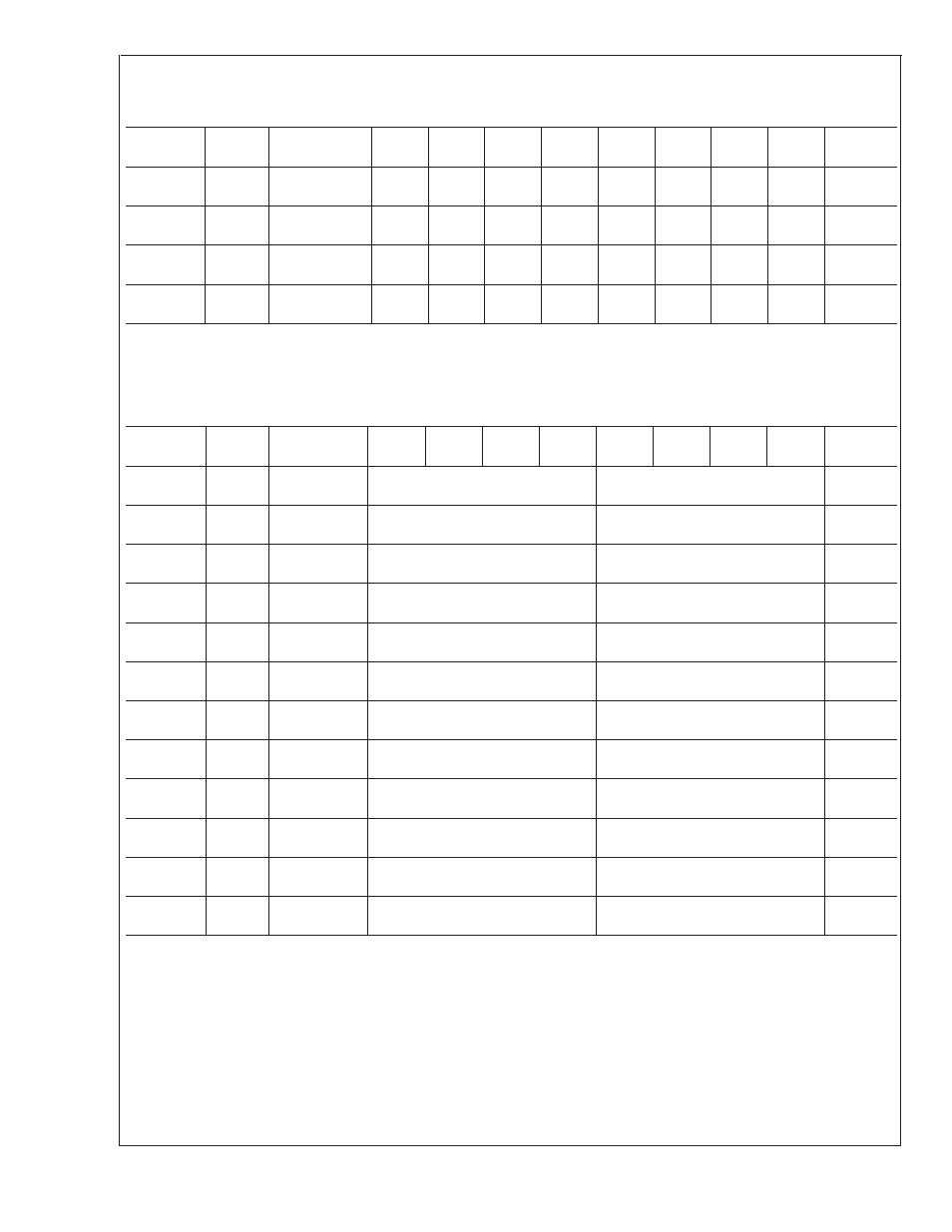
16.8.21 Register D0h–D3h
Zone 1 to 4 Base Temperatures
Register
Address
Read/
Write
Register
Name
Bit 7
Bit 6
Bit 5
Bit 4
Bit 3
Bit 2
Bit 1
Bit 0
Default
Value
D0h
R/W
Zone 1 Base
Temperature
7
6
5
4
3
2
1
0
N/D
D1h
R/W
Zone 2 Base
Temperature
7
6
5
4
3
2
1
0
N/D
D2h
R/W
Zone 3 Base
Temperature
7
6
5
4
3
2
1
0
N/D
D3h
R/W
Zone 4 Base
Temperature
7
6
5
4
3
2
1
0
N/D
The value in this register is used as the base in the temperature calculation for the auto fan control look-up table. These registers
use the standard temperature format (8-bit signed data). The look-up table contains the temperature offsets. The offsets are
added to the base temperature to determine the true temperature to be used for each table entry for auto fan control.
16.8.22 Register D4h–DFh
Lookup Table Steps — Zone 1/2 and Zone 3/4 Offset Temperature
Register
Address
Read/
Write
Register
Name
Bit 7
Bit 6
Bit 5
Bit 4
Bit 3
Bit 2
Bit 1
Bit 0
Default
Value
D4h
R/W
Step 2
Temp Offset
Z3/4_STEP2
Z1/2_STEP2
N/D
D5h
R/W
Step 3
Temp Offset
Z3/4_STEP3
Z1/2_STEP3
N/D
D6h
R/W
Step 4
Temp Offset
Z3/4_STEP4
Z1/2_STEP4
N/D
D7h
R/W
Step 5
Temp Offset
Z3/4_STEP5
Z1/2_STEP5
N/D
D8h
R/W
Step 6
Temp Offset
Z3/4_STEP6
Z1/2_STEP6
N/D
D9h
R/W
Step 7
Temp Offset
Z3/4_STEP7
Z1/2_STEP7
N/D
DAh
R/W
Step 8
Temp Offset
Z3/4_STEP8
Z1/2_STEP8
N/D
DBh
R/W
Step 9
Temp Offset
Z3/4_STEP9
Z1/2_STEP9
N/D
DCh
R/W
Step 10
Temp Offset
Z3/4_STEP10
Z1/2_STEP10
N/D
DDh
R/W
Step 11
Temp Offset
Z3/4_STEP11
Z1/2_STEP11
N/D
DEh
R/W
Step 12
Temp Offset
Z3/4_STEP12
Z1/2_STEP12
N/D
DFh
R/W
Step 13
Temp Offset
Z3/4_STEP13
Z1/2_STEP13
N/D
There are two look up tables of 13 steps (12 offsets), one for Zones 1 and 2 the other for Zones 3 and 4. Each 8-bit offset register
contains the offset temperature for Zones 1 and 2 as well as the offset temperature for Zones 3 and 4. The format for the offsets
is a 4-bit unsigned value, and one LSB = 1˚C.
See the Section 15.10 FAN CONTROL for information on how the base temperature/lookup table should be used for controlling
the PWM output(s).
LM93
www.national.com
76