0 registers – Rainbow Electronics LM93 User Manual
Page 37
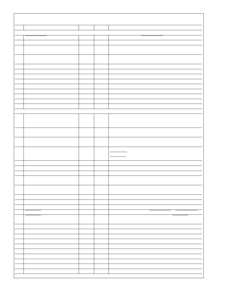
16.0 Registers
(Continued)
Lock
Register Name
Address
Default
Description
LIMIT REGISTERS
P2_PROCHOT User Limit
B1h
FFh
User settable limit for P2_PROCHOT
Vccp1 Limit Offsets
B2h
17h
VID offset values for window comparator for CPU1 Vccp
(AD_IN7)
Vccp2 Limit Offsets
B3h
17h
VID offset values for window comparator for CPU2 Vccp
(AD_IN8)
FAN Tach 1 Limit LSB
B4h
FCh
FAN Tach 1 Limit LSB
FAN Tach 1 Limit MSB
B5h
FFh
FAN Tach 1 Limit MSB
FAN Tach 2 Limit LSB
B6h
FCh
FAN Tach 2 Limit LSB
FAN Tach 2 Limit MSB
B7h
FFh
FAN Tach 2 Limit MSB
FAN Tach 3 Limit LSB
B8h
FCh
FAN Tach 3 Limit LSB
FAN Tach 3 Limit MSB
B9h
FFh
FAN Tach 3 Limit MSB
FAN Tach 4 Limit LSB
BAh
FCh
FAN Tach 4 Limit LSB
FAN Tach 4 Limit MSB
BBh
FFh
FAN Tach 4 Limit MSB
SETUP REGISTERS
x
Special Function Control 1
BCh
00h
Controls the hysteresis for voltage limit comparisons. Also
selects filtered or unfiltered temperature usage for temperature
limit comparisons and fan control.
x
Special Function Control 2
BDh
00h
Enables smart tach detection. Also selects 0.5˚C or 1.0˚C
resolution for fan control.
x
GPI / VID Level Control
BEh
00h
Control the input threshold levels for the P1_VIDx, P2_VIDx
and GPIO_x inputs.
x
PWM Ramp Control
BFh
00h
Controls the ramp rate of the PWM duty cycle when
VRDx_HOT is asserted, as well as the ramp rate when
PROCHOT exceeds the user threshold.
x
Fan Boost Hysteresis (Zones 1/2)
C0h
44h
Fan Boost Hysteresis for zones 1 and 2
x
Fan Boost Hysteresis (Zones 3/4)
C1h
44h
Fan Boost Hysteresis for zones 3 and 4
x
Zones 1/2 Spike Smoothing Control
C2h
00h
Configures Spike Smoothing for zones 1 and 2
x
Zones 1/2 MinPWM and Hysteresis
C3h
N/D
Controls MinPWM and hysteresis setting for zones 1 and 2
auto-fan control
x
Zones 3/4 MinPWM and Hysteresis
C4h
N/D
Controls MinPWM and hysteresis setting for zones 3 and 4
auto-fan control
GPO
C5h
00h
Controls the output state of the GPIO pins
PROCHOT Override
C6h
00h
Allows manual assertion of P1_PROCHOT or P2_PROCHOT
PROCHOT Time Interval
C7h
11h
Configures the time window over which the PROCHOT inputs
are measured
x
PWM1 Control 1
C8h
0Fh
Controls PWM control source bindings.
x
PWM1 Control 2
C9h
00h
Controls PWM override and output polarity
x
PWM1 Control 3
CAh
00h
Controls PWM spin-up duration and duty cycle
x
PWM1 Control 4
CBh
00h
Frequency control for PWM1.
x
PWM2 Control 1
CCh
0Fh
Controls PWM control source bindings.
x
PWM2 Control 2
CDh
00h
Controls PWM override and output polarity
x
PWM2 Control 3
CEh
00h
Controls PWM spin-up duration and duty cycle
x
Special FunctionPWM2 Control 4
CFh
00h
Frequency control for PWM2
LM93
www.national.com
37