0 server terminology, 0 pin descriptions – Rainbow Electronics LM93 User Manual
Page 10
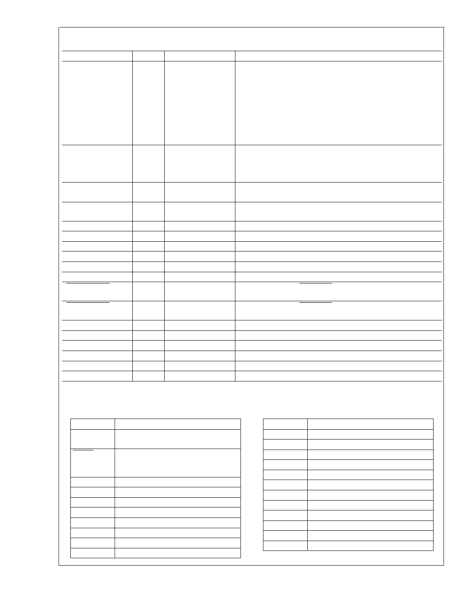
9.0 Pin Descriptions
(Continued)
Symbol
Pin #
Type
Function
AD_IN16
39
POWER (V
DD
) +3.3V
standby power
V
DD
power input for LM93. Generally this is connected to +3.3V
standby power.
The LM93 can be powered by +3.3V if monitoring in low power
states is not required, but power should be applied to this input
before any other pins.
This pin also serves as the analog input to monitor the 3.3V
stand-by (SB) voltage. It is necessary to bypass this pin with a 0.1
µF in parallel with 100 pF. A bulk capacitance of 10 µF should be in
the near vicinity. The 100 pF should be closest to the power pin.
GND
40
GROUND
Digital Ground. Digital ground and analog ground need to be tied
together at the chip then both taken to a low noise system ground.
A voltage difference between analog and digital ground may cause
erroneous results.
PWM1
41
Digital Output
(Open-Drain)
Fan control output 1.
PWM2
42
Digital Output
(Open-Drain)
Fan control output 2
P1_VID0
43
Digital Input
Voltage Identification signal from the processor.
P1_VID1
44
Digital Input
Voltage Identification signal from the processor.
P1_VID2
45
Digital Input
Voltage Identification signal from the processor.
P1_VID3
46
Digital Input
Voltage Identification signal from the processor.
P1_VID4
47
Digital Input
Voltage Identification signal from the processor.
P1_VID5
48
Digital Input
Voltage Identification signal from the processor.
P1_PROCHOT
49
Digital I/O
(Open-Drain)
Connected to CPU1 PROCHOT (processor hot) signal through a
bidirectional level shifter.
P2_PROCHOT
50
Digital I/O
(Open-Drain)
Connected to CPU2 PROCHOT (processor hot) signal through a
bi-directional level shifter.
P2_VID0
51
Digital Input
Voltage Identification signal from the processor.
P2_VID1
52
Digital Input
Voltage Identification signal from the processor.
P2_VID2
53
Digital Input
Voltage Identification signal from the processor.
P2_VID3
54
Digital Input
Voltage Identification signal from the processor.
P2_VID4
55
Digital Input
Voltage Identification signal from the processor.
P2_VID5
56
Digital Input
Voltage Identification signal from the processor.
The overscore indicates the signal is active low (“Not”).
10.0 Server Terminology
A/D
Analog to Digital Converter
ACPI
Advanced Configuration and Power
Interface
ALERT
SMBus signal to bus master that an event
occurred that has been flagged for
attention.
ASF
Alert Standard Format
BMC
Baseboard Micro-Controller
BW
Bandwidth
DIMM
Dual inline memory module
DP
Dual-processor
ECC
Error checking and correcting
FRU
Field replaceable unit
FSB
Front side bus
FW
Firmware
Gb
Gigabit
GB
Gigabyte
Gbe
Gigabit Ethernet
GPIO
General purpose I/O
HW
Hardware
I
2
C
Inter integrated circuit (bus)
LAN
Local area network
LVDS
Low-Voltage Differential Signaling
Mb
Megabit
MB
Megabyte
MP
Multi-processor
MTBF
Mean time between failures
LM93
www.national.com
10