14 register c9hpwm1 control 2, 14 register c9h, Pwm1 control 2 – Rainbow Electronics LM93 User Manual
Page 71: 0 registers
16.0 Registers
(Continued)
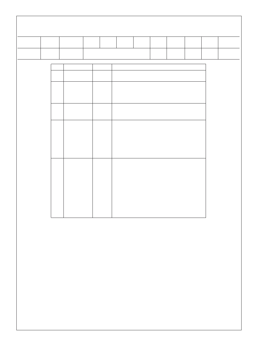
16.8.14 Register C9h
PWM1 Control 2
Register
Address
Read/
Write
Register
Name
Bit 7
Bit 6
Bit 5
Bit 4
Bit 3
Bit 2
Bit 1
Bit 0
Default
Value
C9h
R/W
PWM1
Control 2
OVR_DC
PL
EPPL
INV
OVR
00h
Bit
Name
R/W
Description
0
OVR
R/W
When set, enables manual duty cycle override for
PWM1.
1
INV
R/W
Invert PWM1 output. When 0, 100% duty cycle
corresponds to the PWM output continuously HIGH.
When 1, 100% duty cycle corresponds to the PWM
output continuously LOW.
2
EPPL
R/W
Enable PROCHOT PWM1 lock. When set, this bit
causes bound PROCHOT events on PWM1 to trigger
PPL (bit [3]). When cleared, PPL never gets set.
3
PPL
R/W
PROCHOT PWM1 lock. When set, this bit indicates
that PWM1 is currently being held at 100% because a
bound PROCHOT event occurred while EPPL (bit [2])
was set. This bit is cleared by writing a zero. Clearing
this bit allows the fans to return to normal operation.
This bit is not locked by the LOCK bit in the LM93
Configuration register.
7:4
OVR_DC
R/W
This field sets the duty cycle that will be used by
PWM1 whenever manual override mode is active.
This field accepts 16 possible values that are mapped
to duty cycles according the table in the Fan Control
section. Whenever this register is read, it returns the
duty cycle that is currently being used by PWM1
regardless of whether override mode is active or not.
The value read may not match the last value written if
another control source is requesting a greater duty
cycle. This field always returns 0h when the PWM1
spin up cycle is active.
LM93
www.national.com
71