Zone 1/2 (cpu1 and cpu2) table, Zone 3/4 (lm93 ambient and external ambient) table, 2 fan control temperature resolution – Rainbow Electronics LM93 User Manual
Page 30: Table zone 1/2 (cpu1 and cpu2) table, To table zone 1/2 (cpu1 and cpu2) table, 0 using the lm93
15.0 Using The LM93
(Continued)
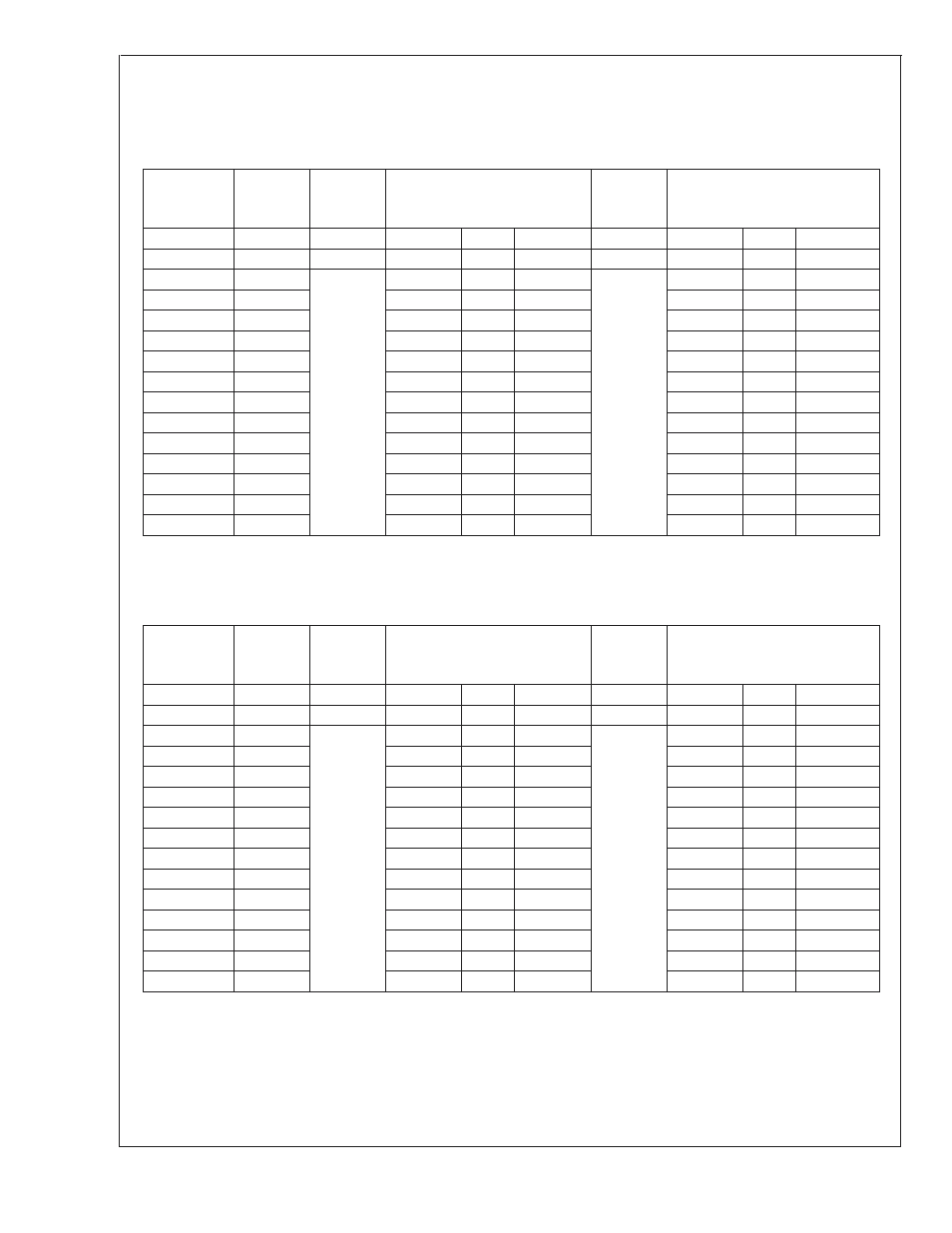
Zone 1/2 (CPU1 and CPU2) Table
In this example: Zones 1 and 2 are bound to the PWM1 output and the PWM1 frequency set to a value in the low range;
Hysteresis is set to 2˚C; Toffset and hysteresis resolution is set to 0.5˚C; minPWM register set to 05h for Zones 1/2. Note,
the duty cycle assignment depends on the zone to PWM output binding and the frequency setting of that PWM output.
Lookup
Table
Duty Cycle
Zone 1/2
Toffset
table
Tbase
CPU1,
Zone1
CPU1 Thermal Diode, Zone 1
(T
D
)
Tbase
CPU2,
Zone2
CPU2 Thermal Diode, Zone 2
(T
D
)
(%)
(˚C)
(˚C)
(˚C)
(˚C)
(˚C)
(˚C)
(˚C)
70
T
D
<
70
60
T
D
<
60
25
0
28.57
0
32.14
0
35.71
0
39.29
0
42.86
0.5
70
≤T
D
<
70.5
60
≤T
D
<
60.5
46.43
1.5
70.5
≤T
D
<
72
60.5
≤T
D
<
62
50
2
72
≤T
D
<
74
62
≤T
D
<
64
53.57
0
57.14
1
74
≤T
D
<
75
64
≤T
D
<
65
71.43
1.5
75
≤T
D
<
76.5
65
≤T
D
<
66.5
85.71
1.5
76.5
≤T
D
<
78
66.5
≤T
D
<
68
100
78
≤T
D
68
≤T
D
Zone 3/4 (LM93 Ambient and External Ambient) Table
In this example: Zone 3 and Zone 4 are bound to the PWM 2 output and the PWM2 output frequency set to 22.5kHz; Hys-
teresis is set to 1˚C; Toffset and hysteresis resolution set to 0.5˚C; minPWM for Zones 3/4 register is set to 06h. Note, the
duty cycle assignment depends on the zone to PWM output binding and the frequency setting of that PWM output.
Lookup
Table
Duty Cycle
Zone 3/4
Toffset
table
Tbase
LM93
Ambient
LM93 Ambient, Zone 3 (T
A
)
Tbase
External
Ambient
External Ambient, Zone 4 (T
A
)
(%)
(˚C)
(˚C)
(˚C)
(˚C)
(˚C)
(˚C)
(˚C)
30
T
A
<
30
35
T
A
<
35
25
0
31.25
0
37.5
0
43.75
0
50
0
56.25
0
62.5
1
30
≤T
A
<
31
35
≤T
A
<
36
68.75
1
31
≤T
A
<
32
36
≤T
A
<
37
75
1
32
≤T
A
<
33
37
≤T
A
<
38
81.25
0.5
33
≤T
A
<
33.5
38
≤T
A
<
38.5
87.5
0.5
33.5
≤T
A
<
34
38.5
≤T
A
<
39
93.75
0.5
34
≤T
A
<
34.5
39
≤T
A
<
39.5
100
34.5
≤T
A
39.5
≤T
A
15.10.2 Fan Control Temperature Resolution
As shown in the example the auto fan control algorithm can
operate in a mode that allows 0.5˚C of temperature resolu-
tion instead of the normal 1˚C. When this mode is enabled,
the temperature offset registers that make up the lookup
table are interpreted differently. One LSB represents 0.5˚C,
and the available range between each datapoint is 0˚C to
7.5˚C instead of 0˚C to 15˚C. In addition, the hysteresis
registers for auto fan control are interpreted in the same way
(one LSB equals 0.5˚C).
Zones 1, 2 and 3 all have 9-bits of internal resolution, which
makes this feature useful. Zone 4 is written in from the
SMBus and only has 8-bits of resolution. The LM93 left
justifies the value into a 9-bit field before using it, if the 0.5˚C
mode is enabled.
LM93
www.national.com
30