7 limit registers, 1 registers 78-7fhtemperature limit registers, 2 registers 80-83hfan boost temperature registers – Rainbow Electronics LM93 User Manual
Page 57: 1 registers 78–7fh, Temperature limit registers, 2 registers 80–83h, Fan boost temperature registers, 0 registers
16.0 Registers
(Continued)
16.7 LIMIT REGISTERS
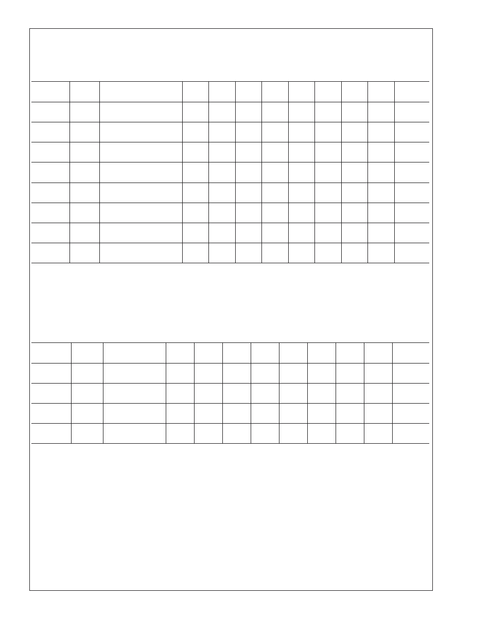
16.7.1 Registers 78–7Fh
Temperature Limit Registers
Register
Address
Read/
Write
Register
Name
Bit 7
Bit 6
Bit 5
Bit 4
Bit 3
Bit 2
Bit 1
Bit 0
Default
Value
78h
R/W
Processor 1 (Zone1)
Low Temp
7
6
5
4
3
2
1
0
80h
79h
R/W
Processor 1 (Zone1)
High Temp
7
6
5
4
3
2
1
0
80h
7Ah
R/W
Processor 2 (Zone2)
Low Temp
7
6
5
4
3
2
1
0
80h
7Bh
R/W
Processor 2 (Zone2)
High Temp
7
6
5
4
3
2
1
0
80h
7Ch
R/W
Internal (Zone3)
Low Temp
7
6
5
4
3
2
1
0
80h
7Dh
R/W
Internal (Zone3)
High Temp
7
6
5
4
3
2
1
0
80h
7Eh
R/W
External Digital (Zone4)
Low Temp
7
6
5
4
3
2
1
0
80h
7Fh
R/W
External Digital (Zone4)
High Temp
7
6
5
4
3
2
1
0
80h
If an external temperature input or the internal temperature sensor either exceeds the value set in the high limit register or falls
below the value set in the low limit register, the corresponding bit in the B_ and H_Error Status 1 register is set automatically by
the LM93. For example, if the temperature read from the Remote1− and Remote1+ inputs exceeds the Processor (Zone1) High
Temp register limit setting, the ZN1_ERR bit in both B_Error Status 1 and H_Error Status 1 registers is set. The temperature limits
in these registers is represented as 8 bit, 2’s complement, signed numbers in Celsius.
If any high temp limit register is set to 80h then the B_ and H_Error Status register bit for that temperature channel is masked.
16.7.2 Registers 80–83h
Fan Boost Temperature Registers
Register
Address
Read/
Write
Register
Name
Bit 7
Bit 6
Bit 5
Bit 4
Bit 3
Bit 2
Bit 1
Bit 0
Default
Value
80h
R/W
Fan Boost Temp
Zone 1
7
6
5
4
3
2
1
0
3Ch
81h
R/W
Fan Boost Temp
Zone 2
7
6
5
4
3
2
1
0
3Ch
82h
R/W
Fan Boost Temp
Zone 3
7
6
5
4
3
2
1
0
23h
83h
R/W
Fan Boost Temp
Zone 4
7
6
5
4
3
2
1
0
23h
If any thermal zone exceeds the temperature set in the Fan Boost Limit register, both of the PWM outputs are set to 100%. The
fan boost function takes precedence over manual override. This is a safety feature that attempts to cool the system if there is a
potentially catastrophic thermal event. If set to 7Fh and the fan control temperature resolution is 1˚C, the feature is disabled.
Default = 60˚C = 3Ch for zones 1 and 2
Default = 35˚C = 23h for zones 3 and 4
The temperature has to fall the number of degrees specified in the Fan Boost Hysteresis registers, below this temperature to
cause the PWM outputs to return to normal operation.
LM93
www.national.com
57