4 register bfhpwm ramp control, 5 register c0hfan boost hysteresis (zones 1/2), 4 register bfh – Rainbow Electronics LM93 User Manual
Page 64: Pwm ramp control, 5 register c0h, Fan boost hysteresis (zones 1/2), 0 registers
16.0 Registers
(Continued)
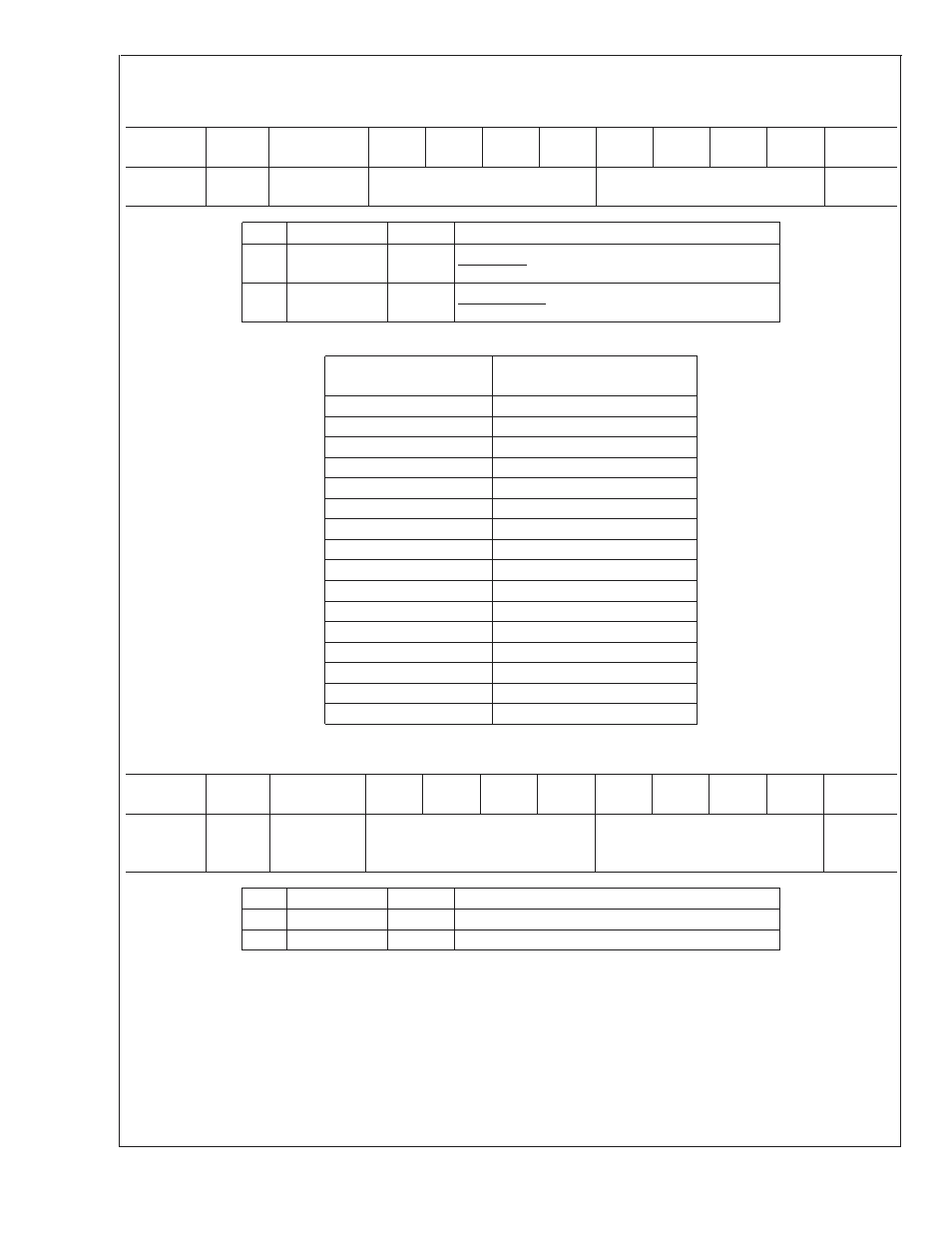
16.8.4 Register BFh
PWM Ramp Control
Register
Address
Read/
Write
Register
Name
Bit 7
Bit 6
Bit 5
Bit 4
Bit 3
Bit 2
Bit 1
Bit 0
Default
Value
BFh
R/W
PWM Ramp
Control
PH_RAMP
VRD_RAMP
00h
Bit
Name
R/W
Description
3:0
VRD_RAMP
R/W
Sets the time delay between ramp steps for the
VRDx_HOT ramp up/ramp down PWM function.
7:4
PH_RAMP
R/W
Sets the time delay between ramp steps for the
Px_PROCHOT ramp up/ramp down PWM function.
If the time delay between steps is set to 0 ms, the PWM duty cycle goes immediately to 100% instead of ramping up gradually.
VRD_RAMP
or PH_RAMP
Time Delay between
Ramp Steps
0h
0 ms
1h
50 ms
2h
100 ms
3h
150 ms
4h
200 ms
5h
250 ms
6h
300 ms
7h
350 ms
8h
400 ms
9h
450 ms
Ah
500 ms
Bh
550 ms
Ch
600 ms
Dh
650 ms
Eh
700 ms
Fh
750 ms
16.8.5 Register C0h
Fan Boost Hysteresis (Zones 1/2)
Register
Address
Read/
Write
Register
Name
Bit 7
Bit 6
Bit 5
Bit 4
Bit 3
Bit 2
Bit 1
Bit 0
Default
Value
C0h
R/W
Fan Boost
Hysteresis
(Zones 1/2)
H2
H1
44h
Bit
Name
R/W
Description
3:0
H1
R/W
Sets the fan boost hysteresis for zone 1
7:4
H2
R/W
Sets the fan boost hysteresis for zone 2
If the temperature zone is above fan boost temperature and then drops below the fan boost temperature, the following occurs:
the PWM output remains at 100% until the temperature goes a certain amount below the fan boost temperature. These hysteresis
registers control this amount and can be set anywhere from 0˚C to 15˚C (unsigned).
LM93
www.national.com
64