Digital thermometer characteristics, Ac electrical characteristics, Quick-trip timing characteristics – Rainbow Electronics DS1876 User Manual
Page 7: I2c ac electrical characteristics, C ac electrical characteristics, Ds1876 sfp controller with dual ldd interface
_______________________________________________________________________________________ 7
DS1876
SFP Controller with Dual LDD Interface
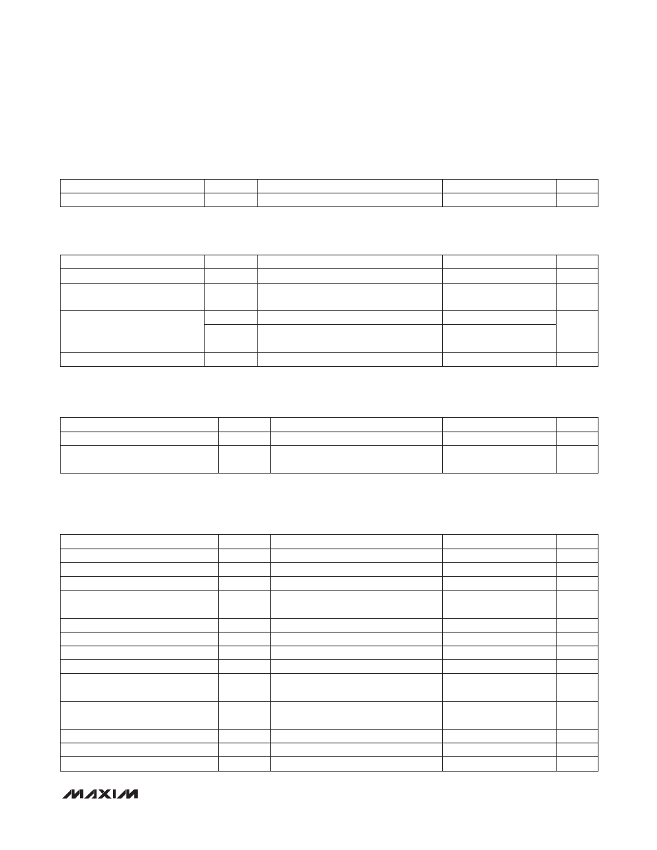
DIGITAL THERMOMETER CHARACTERISTICS
(V
CC
= +2.85V to +3.9V, T
A
= -40NC to +95NC, unless otherwise noted.)
AC ELECTRICAL CHARACTERISTICS
(V
CC
= +2.85V to +3.9V, T
A
= -40NC to +95NC, unless otherwise noted.)
QUICK-TRIP TIMING CHARACTERISTICS
(V
CC
= +2.85V to +3.9V, T
A
= -40NC to +95NC, unless otherwise noted.)
I
2
C AC ELECTRICAL CHARACTERISTICS
(V
CC
= +2.85V to +3.9V, T
A
= -40NC to +95NC, timing referenced to V
IL(MAX)
and V
IH(MIN)
, unless otherwise noted. See the I
2
C
Communication section.)
PARAMETER
SYMBOL
CONDITIONS
MIN
TYP
MAX
UNITS
Thermometer Error
T
ERR
-40NC to +95NC
-3
+3
N
C
PARAMETER
SYMBOL
CONDITIONS
MIN
TYP
MAX
UNITS
TXD_ Enable
t
OFF
From
↑ TXD_
5
F
s
Recovery from TXD_ Disable
(Figure 2)
t
ON
From
↓ TXD_
1
ms
Fault Reset Time (to TXFOUT = 0)
t
INITR1
From
↓ TXD_
131
ms
t
INITR2
On power-up or
↓ TXD_, when VCC LO
alarm is detected (Note 5)
161
Fault Assert Time (to TXFOUT = 1)
t
FAULT
After HTXP_, LTXP_, HBATH_
1.6
10.5
F
s
PARAMETER
SYMBOL
CONDITIONS
MIN
TYP
MAX
UNITS
Output-Enable Time Following POA
t
INIT
20
ms
Sample Time per Quick-Trip
Comparison
t
REP
1.6
F
s
PARAMETER
SYMBOL
CONDITIONS
MIN
TYP
MAX
UNITS
SCL Clock Frequency
f
SCL
(Note 6)
0
400
kHz
Clock Pulse-Width Low
t
LOW
1.3
F
s
Clock Pulse-Width High
t
HIGH
0.6
F
s
Bus Free Time Between STOP and
START Condition
t
BUF
1.3
F
s
START Hold Time
t
HD:STA
0.6
F
s
START Setup Time
t
SU:STA
0.6
F
s
Data Out Hold Time
t
HD:DAT
0
0.9
F
s
Data In Setup Time
t
SU:DAT
100
ns
Rise Time of Both SDA and SCL
Signals
t
R
(Note 7)
20 +
0.1C
B
300
ns
Fall Time of Both SDA and SCL
Signals
t
F
(Note 7)
20 +
0.1C
B
300
ns
STOP Setup Time
t
SU:STO
0.6
F
s
Capacitive Load for Each Bus Line
C
B
400
pF
EEPROM Write Time
t
WR
(Note 8)
20
ms