I2c protocol, C protocol, Figure 13. example i – Rainbow Electronics DS1876 User Manual
Page 21: C timing, Ds1876 sfp controller with dual ldd interface, See figure 13 for an example of i
______________________________________________________________________________________ 21
DS1876
SFP Controller with Dual LDD Interface
always the second byte transmitted during a write
operation following the slave address byte.
I
2
C Protocol
See Figure 13 for an example of I
2
C timing.
Writing a Single Byte to a Slave: The master must
generate a START condition, write the slave address
byte (R/W = 0), write the memory address, write
the byte of data, and generate a STOP condition.
Remember that the master must read the slave’s
acknowledgement during all byte write operations.
Writing Multiple Bytes to a Slave: To write multiple
bytes to a slave, the master generates a START condi-
tion, writes the slave address byte (R/W = 0), writes
the memory address, writes up to 8 data bytes, and
generates a STOP condition. The DS1876 writes 1 to
8 bytes (one page or row) with a single write trans-
action. This is internally controlled by an address
counter that allows data to be written to consecutive
addresses without transmitting a memory address
before each data byte is sent. The address counter
limits the write to one 8-byte page (one row of the
memory map). Attempts to write to additional pages
of memory without sending a STOP condition between
pages result in the address counter wrapping around
to the beginning of the present row.
For example: A 3-byte write starts at address 06h and
writes three data bytes (11h, 22h, and 33h) to three
“consecutive” addresses. The result is that addresses
06h and 07h would contain 11h and 22h, respec-
tively, and the third data byte, 33h, would be written
to address 00h.
To prevent address wrapping from occurring, the
master must send a STOP condition at the end of
the page, then wait for the bus-free or EEPROM write
time to elapse. Then the master can generate a new
START condition and write the slave address byte
(R/W = 0) and the first memory address of the next
memory row before continuing to write data.
Acknowledge Polling: Any time a EEPROM page is
written, the DS1876 requires the EEPROM write time
(t
WR
) after the STOP condition to write the contents of
the page to EEPROM. During the EEPROM write time,
the DS1876 does not acknowledge its slave address
because it is busy. It is possible to take advantage
of that phenomenon by repeatedly addressing the
DS1876, which allows the next page to be written
as soon as the DS1876 is ready to receive the data.
The alternative to acknowledge polling is to wait for
maximum period of t
WR
to elapse before attempting
to write again to the DS1876.
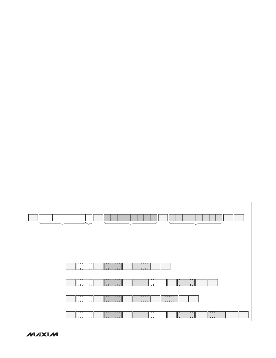
Figure 13. Example I
2
C Timing
START
START
STOP
SLAVE
ACK
SLAVE
ACK
STOP
SINGLE-BYTE WRITE
-WRITE 00h TO REGISTER BAh
TWO-BYTE WRITE
-WRITE 01h AND 75h TO
REGISTERS C8h AND C9h
SINGLE-BYTE READ
-READ REGISTER BAh
TWO-BYTE READ
-READ C8h AND C9h
REPEATED
START
MASTER
NACK
1 0 1 0 0 0 1 0
A2h
1 0 1 1 1 0 1 0
BAh
SLAVE
ACK
START
SLAVE
ACK
1 0 1 0 0 0 1 0
A2h
1 0 1 0 0 0 1 1
A3h
1 0 1 1 1 0 1 0
BAh
SLAVE
ACK
SLAVE
ACK
STOP
0 0 0 0 0 0 0 0
00h
STOP
SLAVE
ACK
STOP
0 1 1 1 0 1 0 1
75h
START
SLAVE
ACK
1 0 1 0 0 0 1 0
A2h
1 1 0 0 1 0 0 0
C8h
SLAVE
ACK
SLAVE
ACK
0 0 0 0 0 0 0 1
01h
SLAVE
ACK
DATA IN BAh
DATA
REPEATED
START
MASTER
ACK
START
SLAVE
ACK
1 0 1 0 0 0 1 0
A2h
1 0 1 0 0 0 1 1
A3h
1 1 0 0 1 0 0 0
C8h
SLAVE
ACK
SLAVE
ACK
DATA IN C8h
DATA
MASTER
NACK
DATA IN C9h
DATA
EXAMPLE I
2
C TRANSACTIONS WITH A2h AS THE SLAVE ADDRESS
*IF ASEL IS 0, THE SLAVE ADDRESS IS A0h FOR THE AUXILIARY MEMORY AND A2h/B2h FOR THE MAIN MEMORY.
IF ASEL = 1, THE SLAVE ADDRESS IS DETERMINED BY TABLE 02h, REGISTER 8Bh FOR THE MAIN MEMORY. THE AUXILIARY MEMORY CONTINUES TO BE ADDRESSED AT A0h, EXCEPT WHEN THE PROGRAMMED
ADDRESS FOR THE MAIN MEMORY IS A0h.
TYPICAL I
2
C WRITE TRANSACTION
A)
C)
B)
D)
MSB
LSB
b7
b6
b5
b4
b3
b2
b1
b0
REGISTER ADDRESS
MSB
LSB
b7
b6
b5
b4
b3
b2
b1
b0
DATA
SLAVE
ACK
SLAVE
ACK
SLAVE
ADDRESS*
X
X
X
X
0
0
1
R/W
MSB
LSB
READ/
WRITE