Typical operating circuit, Detailed description, Dacs during power-up – Rainbow Electronics DS1876 User Manual
Page 12: Typical operating circuit detailed description, Ds1876 sfp controller with dual ldd interface
12 _____________________________________________________________________________________
DS1876
SFP Controller with Dual LDD Interface
Detailed Description
The DS1876 integrates the control and monitoring func-
tionality required in a dual transmitter system. Key com-
ponents of the DS1876 are shown in the Block Diagram
and described in subsequent sections.
DACs During Power-Up
On power-up, the DS1876 sets the DACs to high imped-
ance. After time t
INIT
, the DACs are set to an initial condition
set in EEPROM. After a temperature conversion is com-
pleted and if the VCC LO alarm is enabled, an additional
V
CC
conversion above the customer-defined VCC LO
alarm level is required before the DACs are updated with
the value determined by the temperature conversion and
the DAC LUT.
If a fault is detected, and TXD1 and TXD2 are toggled
to re-enable the outputs, the DS1876 powers up fol-
lowing a similar sequence to an initial power-up. The
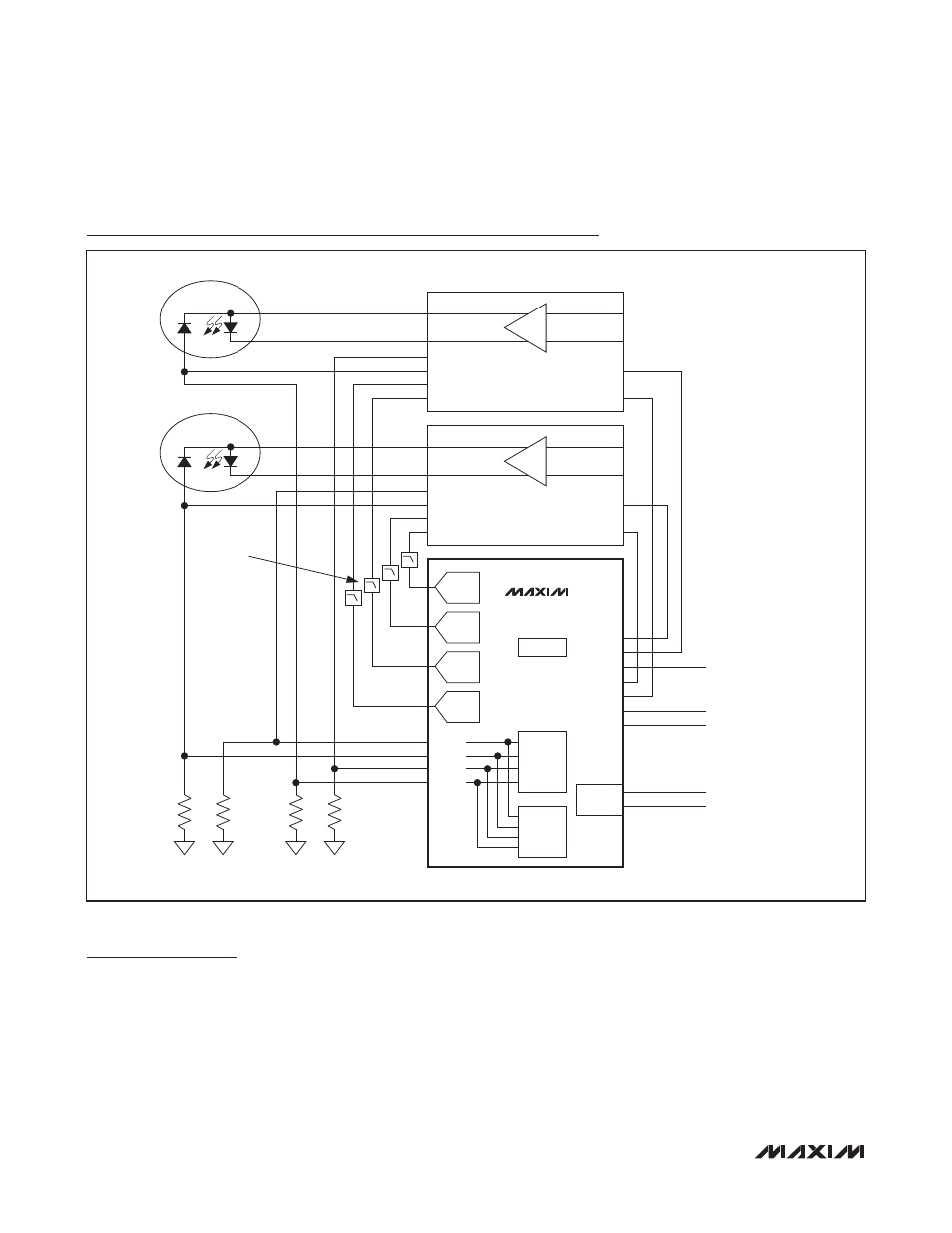
Typical Operating Circuit
TXF1
DISABLE
FAULT
TX_FAULT
TX_DISABLE1
TX_DISABLE2
MOD1
DAC
APC1
DAC
MOD2
DAC
APC2
DAC
LDD1
EEPROM
QUICK
TRIP
ADC
SDA
SCL
TXDOUT2
TXD2
TXDOUT1
TXFOUT
TXF2
TXD1
MODE_DEF2 (SDA)
MODE_DEF1 (SCL)
I
2
C
DS1876
BMON1
PMON1
BMON2
PMON2
BMON
APCIN
APCSET
MODSET
R
B1
R
P2
R
B1
R
P1
TOSA1
DISABLE
FAULT
LDD2
BMON
APCIN
APCSET
MODSET
RC FILTERS
(FIGURE 6)
TOSA2