Monitors and fault detection, Monitors, Six quick-trip monitors and alarms – Rainbow Electronics DS1876 User Manual
Page 14: Six adc monitors and alarms, Figure 3. quick-trip sample timing, Table 2. adc default monitor full-scale ranges, Ds1876 sfp controller with dual ldd interface
14 _____________________________________________________________________________________
DS1876
SFP Controller with Dual LDD Interface
corresponding alarms and warnings (TXP HI1, TXP LO1,
TXP HI2, TXP LO2, BIAS HI1, and BIAS HI2) are asserted
or deasserted.
After resetting, the device completes one QT cycle
before making comparisons. The TXP LO quick-trip
alarm updates its alarm bit, but does not create FETG
until after TXD
EXT
. TXP HI and BIAS HI can also be con-
figured to wait for TXD
EXT
; however, this can be disabled
using QTHEXT_ (Table 02h, Register 88h).
Monitors and Fault Detection
Monitors
Monitoring functions on the DS1876 include six quick-
trip comparators and six ADC channels. This monitoring
combined with the alarm enables (Table 01h/05h) deter-
mines when/if the DS1876 turns off DACs and triggers
the TXFOUT and TXDOUT1, TXDOUT2 outputs. All the
monitoring levels and interrupt masks are user program-
mable.
Six Quick-Trip Monitors and Alarms
Six quick-trip monitors are provided to detect potential
laser safety issues and LOS status. These monitor the
following:
1) High Bias Current 1 (HBATH1), causing QT BIAS1 HI
2) Low Transmit Power 1 (LTXP1), causing QT TXP1 LO
3) High Transmit Power 1 (HTXP1), causing QT TXP1 HI
4) High Bias Current 2 (HBATH2), causing QT BIAS2 HI
5) Low Transmit Power 2 (LTXP2), causing QT TXP2 LO
6) High Transmit Power 2 (HTXP2), causing QT TXP2 HI
The high and low transmit power quick-trip registers
(HTXP1, HTXP2, LTXP1, and LTXP2) set the thresholds
used to compare against the PMON1 and PMON2 volt-
ages to determine if the transmit power is within speci-
fication. The HBATH1 and HBATH2 QTs compare the
BMON1 and BMON2 inputs (generally from the laser
driver’s bias monitor output) against their threshold set-
tings to determine if the present bias current is above
specification. The bias and power QTs are routed to
FETG through interrupt masks to allow combinations
of these alarms to be used to trigger FETG. The bias
and power QTs are directly connected to TXFOUT (see
Figure 9). The user can program up to eight different
temperature-indexed threshold levels for HBATH1 and
HBATH2 (Table 06h, Registers E0h
-E7h).
Six ADC Monitors and Alarms
The ADC monitors six channels that measure tem-
perature (internal temp sensor), V
CC
, PMON1, PMON2,
BMON1, and BMON2 using an analog multiplexer to
measure them round-robin with a single ADC (see the
ADC Timing section). The channels have a customer-
programmable full-scale range, and all channels have a
customer-programmable offset value that is factory pro-
grammed to a default value (see Table 2). Additionally,
PMON1, PMON2 and BMON1, BMON2 can right-shift
results by up to 7 bits before the results are compared
to alarm thresholds or read over the I
2
C bus. This allows
customers with specified ADC ranges to calibrate the
ADC full scale to a factor of 1/2
n
of their specified range
to measure small signals. The DS1876 can then right-
shift the results by n bits to maintain the bit weight of their
specification.
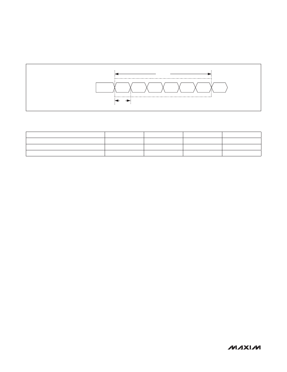
Figure 3. Quick-Trip Sample Timing
Table 2. ADC Default Monitor Full-Scale Ranges
QUICK-TRIP SAMPLE TIMES
LTXP2
SAMPLE
HBIAS1
SAMPLE
HBIAS1
SAMPLE
HBIAS2
SAMPLE
HTXP1
SAMPLE
HTXP2
SAMPLE
LTXP1
SAMPLE
LTXP2
SAMPLE
t
REP
QT CYCLE
SIGNAL (UNITS)
+FS SIGNAL
+FS HEX
-FS SIGNAL
-FS HEX
Temperature (NC)
127.996
7FFF
-128
8000
V
CC
(V)
6.5528
FFF8
0
0000
PMON1, PMON2 and BMON1, BMON2 (V)
2.4997
FFF8
0
0000