Ds1876 sfp controller with dual ldd interface – Rainbow Electronics DS1876 User Manual
Page 37
______________________________________________________________________________________ 37
DS1876
SFP Controller with Dual LDD Interface
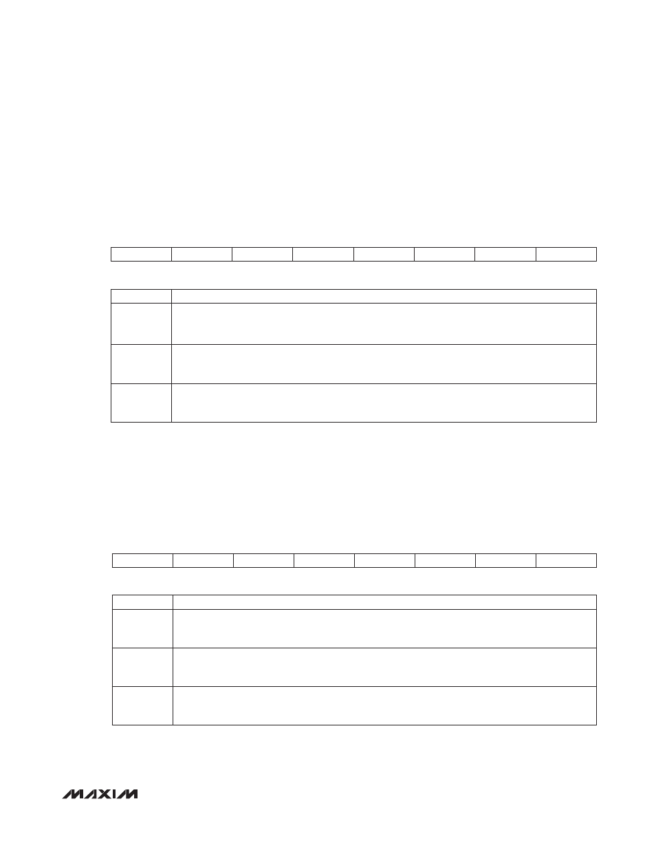
Lower Memory, Register 71h: ALARM
2
Lower Memory, Register 72h: ALARM
1
POWER-ON VALUE
00h
READ ACCESS
All
WRITE ACCESS
N/A
A2h AND B2h MEMORY
Mixed A2h and B2h memory locations
MEMORY TYPE
Volatile
71h
RESERVED
RESERVED
RESERVED
RESERVED
RESERVED
TXFOUTS
FETG
TXFINT
BIT 7
BIT 0
BITS 7:3
RESERVED
BIT 2
TXFOUTS: TXFOUT status. Indicates the state the open-drain output is attempting to achieve.
0 = TXFOUT is pulling low.
1 = TXFOUT is high impedance.
BIT 1
FETG: Status of internal signal FETG. The FETG signal is part of the internal shutdown logic.
0 = (default) FETG is low.
1 = FETG is high.
BIT 0
TXFINT: TXF interrupt. This bit is the wire-ORed logic of all alarms and warnings wire-ANDed with
their corresponding enable bits, plus the wire-ORed logic of HBAL, TXP HI, and TXP LO. The enable
bits are found in Table 01h/05h, Registers F8h–FFh.
POWER-ON VALUE
00h
READ ACCESS
All
WRITE ACCESS
N/A
A2h AND B2h MEMORY
Different A2h and B2h memory locations
MEMORY TYPE
Volatile
72h
RESERVED
RESERVED
RESERVED
RESERVED
HBAL
RESERVED
TXP HI
TXP LO
BIT 7
BIT 0
BITS 7:4, 2
RESERVED
BIT 3
HBAL: High bias alarm status; fast comparison. A TXD event clears this alarm.
0 = (default) Last comparison was below threshold setting.
1 = Last comparison was above threshold setting.
BIT 1
TXP HI: High alarm status TXP; fast comparison. A TXD event clears this alarm.
0 = (default) Last comparison was below threshold setting.
1 = Last comparison was above threshold setting.
BIT 0
TXP LO: Low alarm status TXP; fast comparison. A TXD event clears this alarm.
0 = (default) Last comparison was above threshold setting.
1 = Last comparison was below threshold setting.