Table ii. pipe maximum and minimum wall thickness, 975 combo roll groover – RIDGID Combo Roll Groover User Manual
Page 21
Ridge Tool Company
19
975 Combo Roll Groover
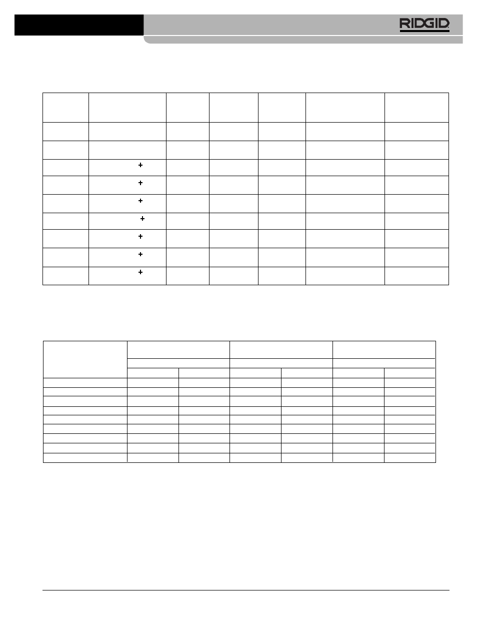
Table I. Standard Roll Groove Specifications For Pipe of IPS Dimensions
NOTE! All Dimensions are in Inches.
T
A
B
C
D
NOM.
PIPE
MIN.
GASKET
GROOVE
GROOVE
NOM.
PIPE
DIAMETER
WALL
SEAT
WIDTH
DIAMETER
GROOVE
SIZE
O.D.
TOL.
THK.
+.015/-.030
+.030/-.015
O.D.
TOL.
DEPTH (Ref.) (2)
1
1
/
4
1.660
+.016
.065
.625
.344
1.535
+.000
.063
-.016
-.015
1
1
/
2
1.900
+.016
.065
.625
.344
1.775
+.000
.063
-.016
-.015
2
(1)
2.375
+
.024
.065
.625
.344
2.250
+.000
.063
-.016
-.015
2
1
/
2
(1)
2.875
+
.029
.083
.625
.344
2.720
+.000
.078
-.016
-.015
3
(1)
3.50
+
.030
.083
.625
.344
3.344
+.000
.078
-.018
-.015
3
1
/
2
(1)
4.00
+
030
.083
.625
.344
3.834
+.000
.083
-.018
-.015
4
(1)
4.50
+
.035
.083
.625
.344
4.334
+.000
.083
-.020
-.015
5
(1)
5.563
+
.056
.109
.625
.344
5.395
+.000
.084
-.022
-.015
6
(1)
6.625
+
.050
.109
.625
.344
6.455
+.000
.085
-.024
-.015
(1) As per AWWA C606-06
(2) Nominal Groove Depth is provided as a reference dimension only. Do not use groove depth to determine acceptability of a groove.
Table II. Pipe Maximum and Minimum Wall Thickness
NOTE! All Dimensions are in Inches.
CARBON STEEL OR
STAINLESS STEEL
ALUMINUM PIPE OR TUBE
PIPE OR TUBE
PVC PIPE
Pipe Size
Wall Thickness
Wall Thickness
Wall Thickness
Min.
Max.
Min.
Max.
Min.
Max.
1
1
/
4
"
.065
.140
.065
.140
.140
.140
1
1
/
2
"
.065
.145
.065
.145
.145
.200
2"
.065
.154
.065
.154
.154
.154
2
1
/
2
"
.083
.203
.083
.188
.203
.276
3"
.083
.216
.083
.188
.216
.300
3
1
/
2
"
.083
.226
.083
.188
.226
.300
4"
.083
.237
.083
.188
.237
.300
5"
.109
.258
.109
.188
.258
.300
6"
.109
.280
.109
.188
.280
.300