Yamaha 006IPTO-F0 User Manual
Page 279
Using GPI (General Purpose Interface)
279
DM1000 Version 2—Owner’s Manual
Other Functions
20
• xxx UNLATCH .............The assigned button function is enabled only while the incom-
ing trigger signal is active.
• xxx ON...........................The corresponding channels are turned on or off each time the
incoming trigger signal becomes active.
• xxx ON UNLATCH......The corresponding channels are turned on only while the
incoming trigger signal is active.
• UDEFxxx.......................Same as the corresponding User Defined buttons.
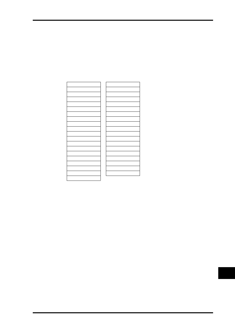
■ Trigger sources available in the OUTPUT section
• xxx FADER ON ............The trigger signal is transmitted when you raise a fader from
–
∞.
• xxx FADER OFF...........The trigger signal is transmitted when you lower a fader to –
∞.
• xxx FADER TALLY.......The trigger signal is transmitted while a fader remains above
–
∞.
• xxx LATCH ...................Pressing the corresponding button toggles the trigger signal on
and off.
• xxx UNLATCH .............The trigger signal is transmitted while you are pressing and
holding down the corresponding button.
• REC LAMP....................The trigger signal is transmitted while the transport section on
the Remote | Machine Control page is in record mode.
• POWER ON ..................The trigger signal is transmitted while the power to the
DM1000 is on.
No Assign
ST FADER OFF
CH1 FADER ON
CH1 FADER TALLY
:
:
CH48 FADER ON
CH48 FADER TALLY
BUS1 FADER ON
BUS1 FADER TALLY
:
:
BUS8 FADER ON
BUS8 FADER TALLY
AUX1 FADER ON
AUX1 FADER TALLY
:
:
AUX8 FADER ON
AUX8 FADER TALLY
ST FADER ON
ST FADER TALLY
CH1 FADER OFF
UDEF1 LATCH
:
:
CH48 FADER OFF
UDEF12 LATCH
BUS1 FADER OFF
UDEF1 UNLATCH
:
:
BUS8 FADER OFF
UDEF12 UNLATCH
AUX1 FADER OFF
REC LAMP
:
POWER ON
AUX8 FADER OFF