Figure 3-3. ipmux-1e front panel indicators – RAD Data comm IPmux-1 User Manual
Page 49
IPmux-1/1E Installation and Operation Manual
Chapter 3 Operation
Front Panel Controls, Connectors, and Indicators
3-3
Table 3-1. IPmux-1 System Indicators and Switches (Cont.)
No. Name
Type
Function
7
ETH FDX
LED
On: Full duplex
Off: Half duplex
8
POWER
Switch
Turns IPmux-1/1E power On and Off
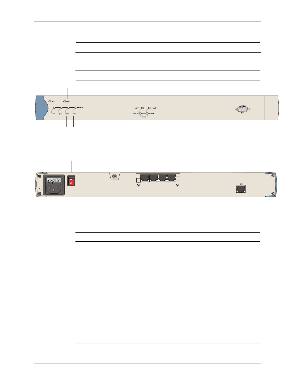
IPmux-1E
1
3
4
5
6
7
2
Figure 3-3. IPmux-1E Front Panel Indicators
100
-2
40 V
A
C
1A
T
2
50V
POWER
I/O
3
:
CAUTION
IISDN
S
1
2
3
4
8
Figure 3-4. IPmux-1E Back Panel Indicators
Table 3-2. IPmux-1E (BRI/FXS) System Indicators and Switches
No. Name
Type Function
1
PS1
Green On: Unit powered
Red On: Power supply failure
Off: Unit not powered
2 RDY
LED On:
Device
OK
Off: Self-test in progress
Blinking: Malfunction detected
3 SYNC
CH1–CH4
LED ISDN
On: ISDN synchronized
Off: ISDN LOF
FXS
On:
OFF
hook
Off: ON hook
Blinking:
Ringing
Order from: Cutter Networks
Ph:727-398-5252/Fax:727-397-9610
www.bestdatasource.com