RAD Data comm IPmux-1 User Manual
Page 44
Chapter 2 Installation
IPmux-1/1E Installation and Operation Manual
2-8 Installation and Setup
Table 2-4. ISDN-S Interface Pin Assignments
Pin Number
Signal Name
3 Tx+
4 Rx+
5 Rx-
6 Tx-
Table 2-5. FXS Interface Pin Assignments for RJ-11
Pin Number Designation
Direction
Function
1,2
Not
connected
3 RING
IN/OUT 2W
input/output
4 TIP
IN/OUT 2W
input/output
5,6
Not
connected
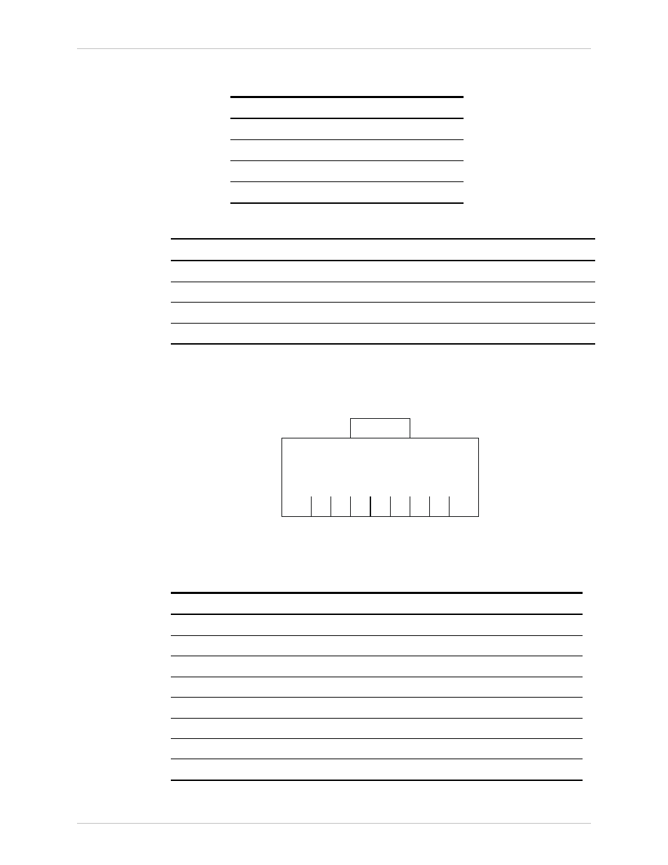
Connecting the Control Port
The Control port is located on the IPmux-1/1E front panel (Figure 2-2). The
External Clock port pinout is shown in Figure 2-10 listed in Table 2-6.
1
2
3
4
5
6
7
8
Figure 2-10. External Clock Port Pinout
Table 2-6. External Clock Port Pinout
Pin Number
Signal Name
Function
RRING
Rx
2 RTIP Rx
3
GND
Usually not connected
4 TRING Tx
5 TTIP Tx
6
GND
Usually not connected
7
Not
connected
8
Not
connected
Order from: Cutter Networks
Ph:727-398-5252/Fax:727-397-9610
www.bestdatasource.com