Mother board – NEC Express5800/120Rh-2 N8100-1126F User Manual
Page 41
General Description 2-9
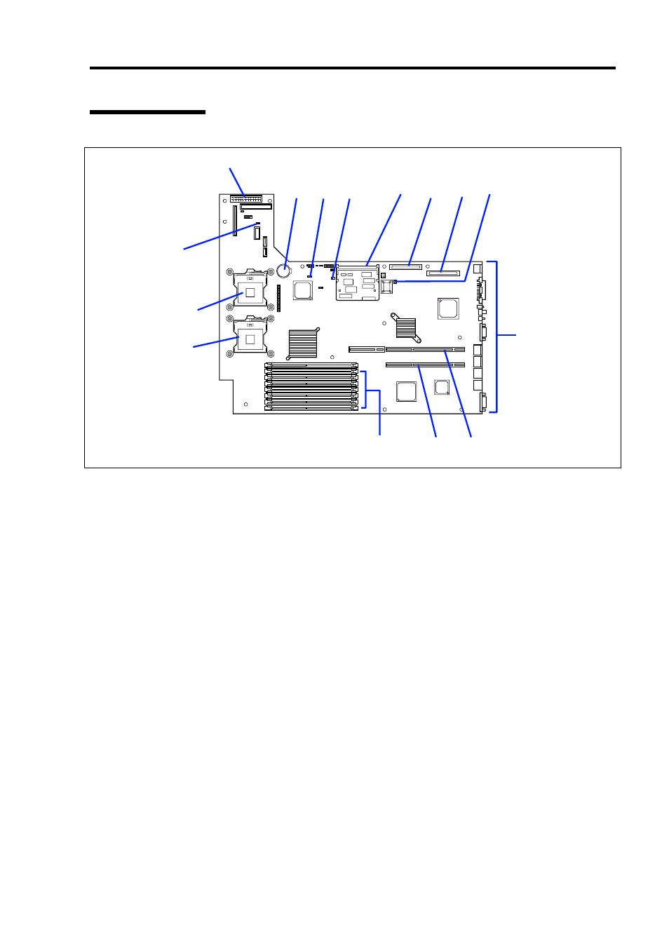
Mother Board
1 Main power connector
2 Lithium battery
3 CMOS clear jumper switch
4 Hard disk drive access LED pin header
(Connect the LED relay cable of an additional SCSI/RAID controller.)
5 Remote management card socket
6 SCSI 1 connector (for SCSI hard disk drives)
7 SCSI 2 connector (for backup file device)
8 Password clear jumper switch
9 Connectors for external device
10 PCI riser card slot
(For full-height boards. 100 MHz/64-bit, 3.3V, PCI-X)
11 PCI riser slot
(For only low-profile boards. 66MHz/64-bit, 3.3V, PCI-X)
12 DIMM sockets (for the interleave type)
(The sockets are called #1, #2, #3, #4, #5, #6, #7, and #8 sequentially from top.)
13 Processor sockets
13-1 Processor #1 (CPU #1)
13-2 Processor #2 (CPU #2)
14 Redundant fan jumper switch
1
2
3
4
5
6
7
8
10
11
12
FRONT
13-1
14
REAR
13-2
9