Figure 2-11. analog output connections, Figure 2-11. analog output connections -30 – National Instruments AT-MIO-16X User Manual
Page 52
Chapter 2
Configuration and Installation
AT-MIO-16X User Manual
2-30
© National Instruments Corporation
The following ranges and ratings apply to the EXTREF input:
Normal input voltage range
±10 V peak with respect to AO GND
Usable input voltage range
±18 V peak with respect to AO GND
Absolute maximum ratings
±30 V peak with respect to AO GND
AO GND is the ground reference point for both analog output channels
and for the external reference signal.
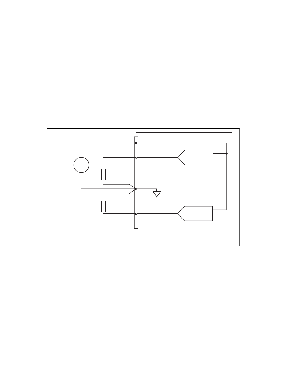
Figure 2-11 shows how to make analog output connections and the
external reference input connection to the AT-MIO-16X board.
Figure 2-11. Analog Output Connections
The external reference signal can be either a DC or an AC signal. This
reference signal is multiplied by the DAC code to generate the output
voltage.
+
-
+
-
+
-
V
ref
Channel 0
Channel 1
External
Reference
Signal
(Optional)
Load
Load
VOUT 0
VOUT 1
DAC1 OUT
AO GND
DAC0 OUT
EXTREF
Analog Output Channels
AT-MIO-16X Board