Initializing the at-mio-16x, Table 5-1. am9513a counter/timer allocations, Initializing the at-mio-16x -2 – National Instruments AT-MIO-16X User Manual
Page 171: Table 5-1, Am9513a counter/timer allocations -2
Chapter 5
Programming
AT-MIO-16X User Manual
5-2
© National Instruments Corporation
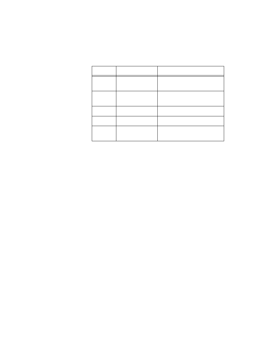
Table 5-1 provides a general overview of the AT-MIO-16X resources
to ensure there are no conflicts when using the counters/timers. As an
example, if an interval scanning data acquisition sequence that requires
less than 65,537 samples is in operation, Counters 2, 3, and 4 of the
Am9513A are reserved for this purpose. This leaves Counters 1 and 5
available for general-purpose or waveform generation use.
Initializing the AT-MIO-16X
The AT-MIO-16X hardware must be initialized for the AT-MIO-16X
circuitry to operate properly. To initialize the AT-MIO-16X hardware,
complete the following steps:
1.
Write 0 to Command Registers <1..4>.
2.
Access the following strobe registers:
CONFIGMEMCLR Register
DAQ Clear Register
DMATC A and B Clear Registers
DMA Channel Clear Register
DAC Clear Register
TMRREQ Clear Register
ADC Calibration Register
3.
Initialize the Am9513A (see Initializing the Am9513A section later
in this chapter).
Table 5-1. Am9513A Counter/Timer Allocations
Counter
DAQ Operation
Waveform Operation
1
Scan division
Updating/cycle counting/pulsed
waveform
2
Scan division
Updating/cycle counting/pulsed
waveform
3
Sample interval
Updating
4
Sample count
N/A
5
Sample count
(> 65,536)
Updating/cycle counting