Digital output register, Digital output register -70 – National Instruments AT-MIO-16X User Manual
Page 166
Chapter 4
Register Map and Descriptions
AT-MIO-16X User Manual
4-70
© National Instruments Corporation
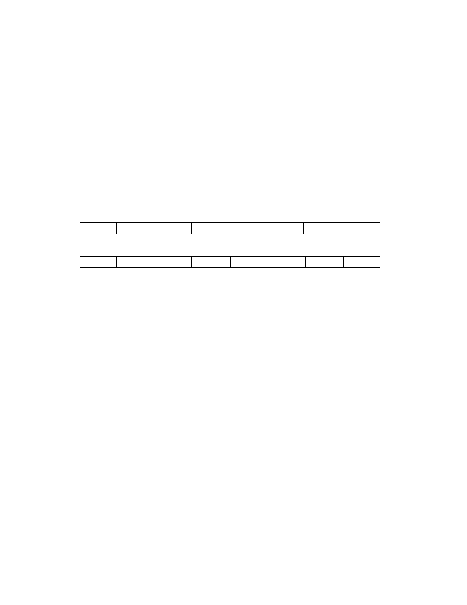
Digital Output Register
Writing to the Digital Output Register controls the eight AT-MIO-16X
digital I/O lines. The Digital Output Register controls both ports A and
B. When either digital port is enabled, the pattern contained in the
Digital Output Register is driven onto the lines of the digital port.
Address:
Base address + 1C (hex)
Type:
Write-only
Word Size:
16-bit
Bit Map:
Bit
Name
Description
15-8
0
Reserved
7-4
BDIO<3..0>
These four bits control the digital lines
BDIO<3..0>. The bit DIOPBEN in
Command Register 2 must be set for
BDIO<3..0> to be driven onto the digital
lines BDIO<3..0>.
3-0
ADIO<3..0>
These four bits control the digital lines
ADIO<3..0>. The bit DIOPAEN in
Command Register 2 must be set for
ADIO<3..0> to be driven onto the digital
lines ADIO<3..0>.
7
6
5
BDIO2
4
3
BDIO0
2
ADIO2
1
0
ADIO1
BDIO3
BDIO1
ADIO0
ADIO3
15
MSB
LSB
14
13
0
12
11
0
10
0
9
8
0
0
0
0
0