Signal connection descriptions, Signal connection descriptions -17 – National Instruments AT-MIO-16X User Manual
Page 39
Chapter 2
Configuration and Installation
© National Instruments Corporation
2-17
AT-MIO-16X User Manual
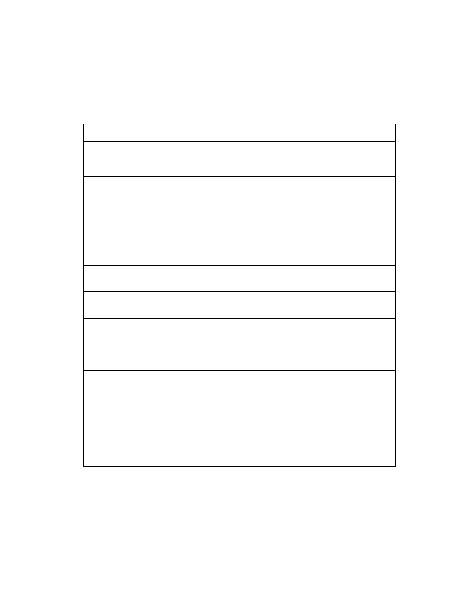
Signal Connection Descriptions
Signal Names
Reference
Descriptions
AI GND
N/A
Analog Input Ground—These pins are the reference point for
single-ended measurements and the bias current return point
for differential measurements.
ACH<0..15>
AI GND
Analog Input Channels 0 through 15—In differential mode,
the input is configured for up to eight channels. In
single-ended mode, the input is configured for up to
16 channels.
AI SENSE
AI GND
Analog Input Sense—This pin serves as the reference node
when the board is in NRSE configuration. If desired, this
signal can be programmed to be driven by the board analog
input ground in the DIFF and RSE analog input modes.
DAC0 OUT
AO GND
Analog Channel 0 Output—This pin supplies the voltage
output of analog output Channel 0.
DAC1 OUT
AO GND
Analog Channel 1 Output—This pin supplies the voltage
output of analog output Channel 1.
EXTREF
AO GND
External Reference—This is the external reference input for
the analog output circuitry.
AO GND
N/A
Analog Output Ground—The analog output voltages are
referenced to this node.
DIG GND
N/A
Digital Ground—This pin supplies the reference for the
digital signals at the I/O connector as well as the +5 VDC
supply.
ADIO<0..3>
DIG GND
Digital I/O port A signals.
BDIO<0..3>
DIG GND
Digital I/O port B signals.
+5 V
DIG GND
+5 VDC Source—These pins are fused for up to 1 A of +5 V
supply.