FUJITSU DL3750+/3850+ User Manual
Page 211
D-9
User's Manual
INTERFACE INFORMATION
Interface
TD
RD
DSR
DTR
RTS
CTS
CD
SG
Host
Printer
(Pin 2)
(Pin 3)
(Pin 6)
(Pin 20)
(Pin 4)
(Pin 5)
(Pin 8)
(Pin 7)
TD
RD
DSR
DTR (RC)
RTS
CTS
CD
SG
#
#
#
#
#
# indicates an open wire.
Wire
q is unnecessary for the DTR (or RC) protocol.
Some computers may not require wire
w.
q
w
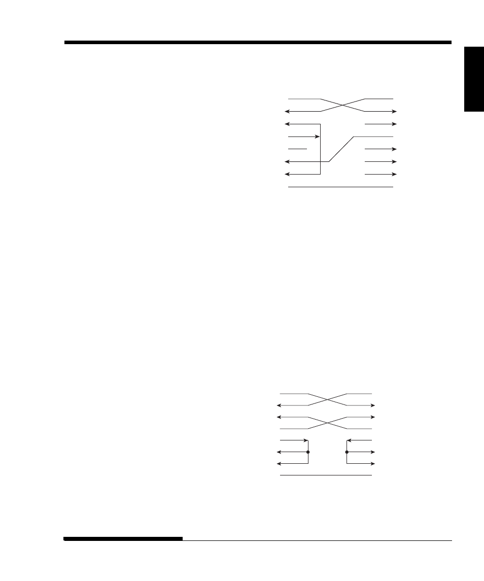
DSR-enabled control enables communication using an RS-232C interface.
The CTS and DSR input control signals are enabled; CD is ignored. DSR
must be high when the printer receives data. If the printer has data to be
transmitted to the computer, the printer transmits the data when both DSR and
CTS are high.
When using DSR-enabled control, use a straight-through cable to connect to a
DCE (data communications equipment) device. Use a null-modem cable to
connect to a DTE (data terminal equipment) device, as shown below.
TD
RD
DSR
DTR
RTS
CTS
CD
SG
Host (DTE)
Printer (DTE)
(Pin 2)
(Pin 3)
(Pin 6)
(Pin 20)
(Pin 4)
(Pin 5)
(Pin 8)
(Pin 7)
TD
RD
DSR
DTR
RTS
CTS
CD
SG
- FTP-633GA1021 (6 pages)
- KA02038-Y820 (1 page)
- FTP-632MCL102 (7 pages)
- FTP-621MCL102 (6 pages)
- FTP-604 FTP-644MCL002 (7 pages)
- FTP-629MCL103-R (7 pages)
- FTP-641MCL351 (6 pages)
- C145-C037-01EN (123 pages)
- FTP-030P (3 pages)
- FTP-627USL401 (9 pages)
- FTP-621CT001 (6 pages)
- FTP-629MCL054 (7 pages)
- FTP-634MCL001 (7 pages)
- FTP-624MCL002 (8 pages)
- Printer (4 pages)
- FTP-040HF Holder Series (2 pages)
- P3PC-1442-01EN (17 pages)
- FTP-631MCL201 (6 pages)
- FTP-628WSL120 (7 pages)
- ScandAll PRO P2WW-2410-01ENZ0 (45 pages)
- DL6400Pro (247 pages)
- FTP-632MCL003 (7 pages)
- FTP-633MCL400 (12 pages)
- FTP-631MCL302 (6 pages)
- 102 (8 pages)
- FTP-622MCL302 (6 pages)
- FTP-642MCL302 (7 pages)
- 16DV (39 pages)
- FTP-639MCL103/383-R (7 pages)
- FTP-637MCL401 (6 pages)
- DL9400 (250 pages)
- M304X (143 pages)
- FTP-631MCL352 (6 pages)
- FTP-631MCL101 (6 pages)
- FTP-639MCL353 (7 pages)
- FTP-641MCL302 (6 pages)
- FTP-622DCL001/011 (8 pages)
- FTP-628MCL401 (9 pages)
- FTP-621MCL201 (6 pages)
- FTP-641MCL101/102 (6 pages)
- FTP-632MCL301 (6 pages)
- DL3800 (262 pages)
- DL6400 (247 pages)
- FTP-627USL631 (10 pages)
- FTP-624MCL304 (7 pages)