Generac Power Systems MC User Manual
Page 82
Attention! The text in this document has been recognized automatically. To view the original document, you can use the "Original mode".
3« 3> 3» 20-Install springs and ret
ainers over tappets. Intake valve
is identified by the letter ”1",
exhaust valve by an
Slide
both velves dovzn through valve
guides, retainers and springs.
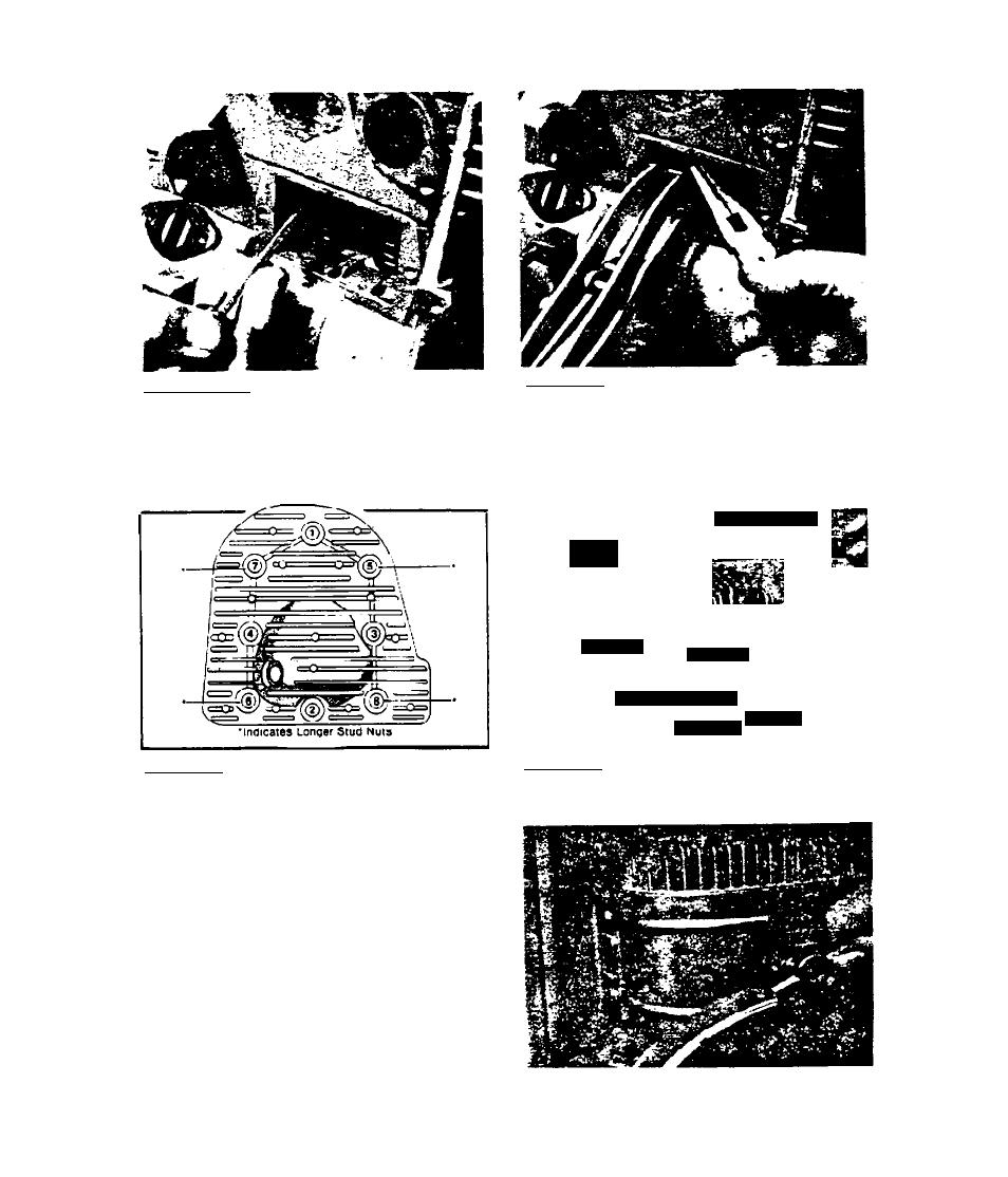
3.3.3.22-Install a new cylinder
head gasket. Install cylinder
head. Location of 4 longer stud
nuts and torque sequence are
shown in illustration.
3. 3. 3. 24-
Install
cowling,
3.3.3.21-Compress valve springs,
using a spring compressor. Then
instali roil pin through hole in
valve stem. Remove compressor
and make sure roll pin is locked
in place by lower valve spring
retainer.
•:4 '
'i-
3.3.3.23-Tlghten head nuts Co 22
29 foot-pounds in sequence shown
in previous illustration.
3.3-12