Generac Power Systems MC User Manual
Page 42
Attention! The text in this document has been recognized automatically. To view the original document, you can use the "Original mode".
RESULT:- Primary windiag rasistance. checks good..Check customer wiring
Primary winding resistance is bad,.......Replace Transformer
NOTE
The Sensing Transformer secondary windings MUST connect to the
Voltage Regulator, The primary windings..must connect to the
white connector plug. In most cases, primary and secondary wi
ndings will be identified when replacing a Transformer. If the
windings are not identified, check winding resistance. The
winding having the HIGHEST resistance is the SECONDARY winding.
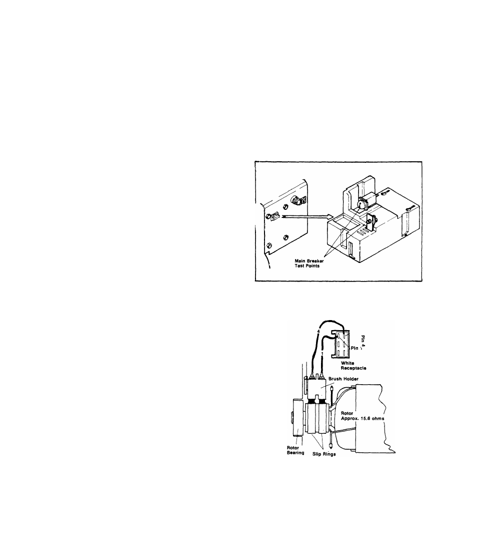
TEST 38:- MAIN CIRCUIT BREAKER
Set VOM to ”+DC" and to "Rxl" scale.
Zero the meter. See illustration at
right. Connect VOM test probes acr
oss the Main Rreaker teat points.
Meter needle should swing upscale to
zero with Main Breaker ON, When the
Breaker is set .to OFF, needle should
drop all the way downscale (infinity),
RESULT:- Main Breaker cheeks good.
Main Breaker feeafes bad.
.Continue diagnostic tests
..........Replace Breaker
TEST 39:- CHECK ROTOR
A.)-Disconnect the white connect
or plug from its receptacle on the
stator can. Set VOM to "+DC” and
to "Rxl” scale, then zero the met
er. Connect the positive (+) meter
test probe to white receptacle Pin
4, Connect the common (-) probe to
receptacle Pin 1, Meter needle
should swing upscale and indicate
rotor winding resistance (approxi
mately 15,6 Ohms),
RESULT:- Rotor checks good
Rotor checks bad..
.... Go to Test 40
,Go to Paragraph B
2.2-20