Generac Power Systems MC User Manual
Page 72
Attention! The text in this document has been recognized automatically. To view the original document, you can use the "Original mode".
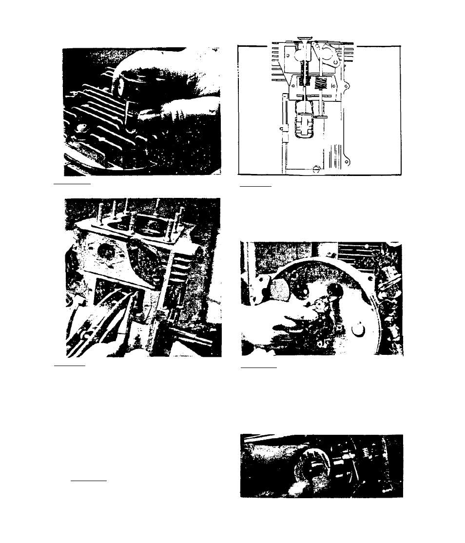
3,3*1« 7-Remove 8 cylinder head uuts.
Remove cylinder head and head gasket:«
3,3«l,9~Use valve spring compressor
Co compress valve springs. Then re
move roller pin from valve stem.
Remove compressor, Chen remove valve
springs, spring rpLaine.rs and valves.
3.3.1.8-Intake and exhausC valves
are shown in a sectional view ab
ove. Valve springs are retained
Co valve stems by valve retainers
and a roller pin. Keep valve parts
together as a set. Intake valve is
identified by the letter ”1” on
3,3.1»10-Drain engine oil. Remove
all bolts chat retain engine bear
ing cover. Rotate crankshaft to
place its keyx^ay at 12:00 position
(top dead center of piston stroke).
Install screws into ignition stator
screw holes. Use these screws and a
puller Co remove bearing cover.
3.3.1.11-Remove thrust washer from
end or cam shaft.
3.3-2