Generac Power Systems MC User Manual
Page 28
Attention! The text in this document has been recognized automatically. To view the original document, you can use the "Original mode".
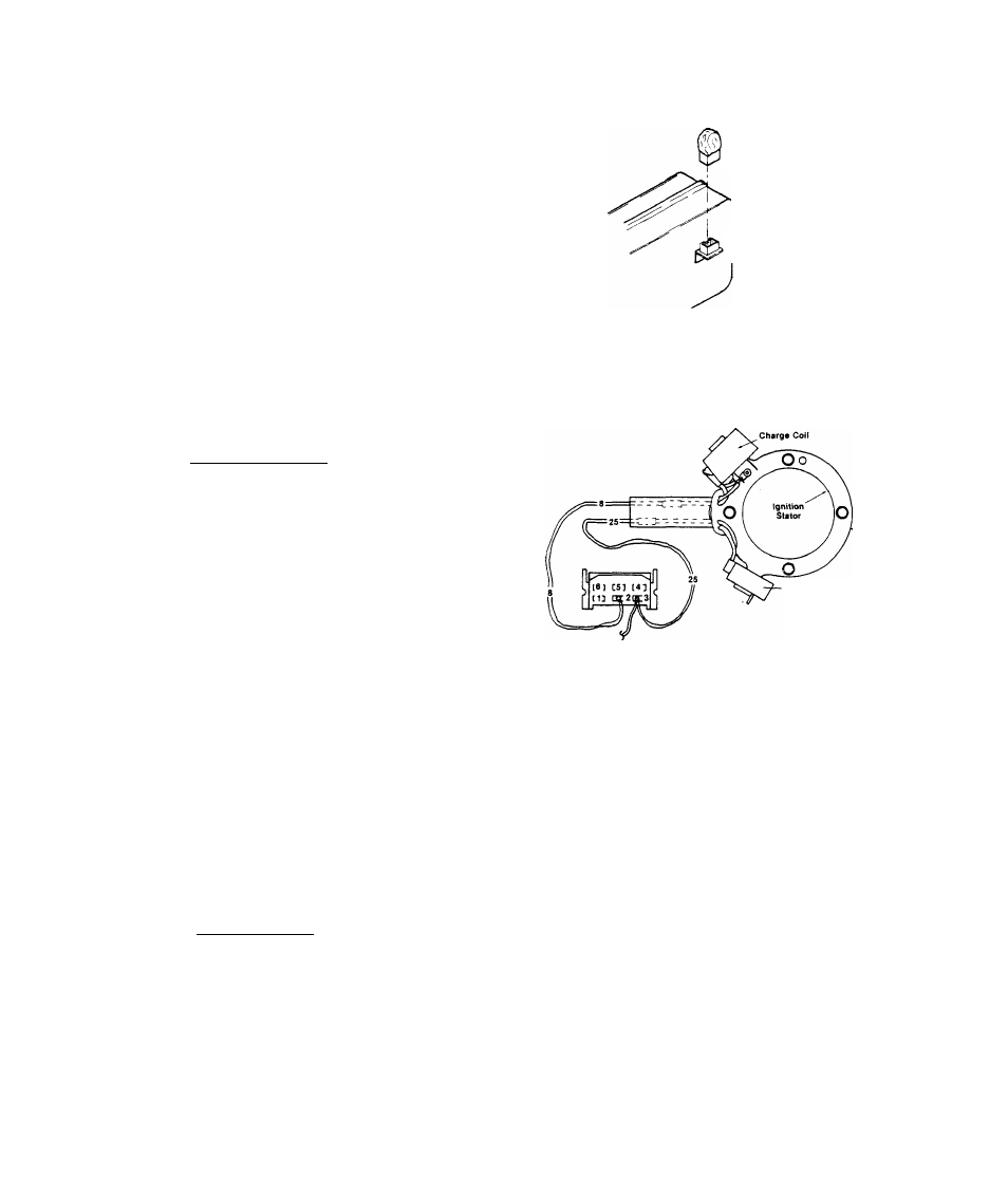
TEST 12- IGNITION MODULE
Unplug the Ignition Module from
its receptacle on the side of the
stator can. Carefully inspect mo
dule and receptacle pins for. dam
age, bending or "pushing out"
from their retainers. Plug in a
known good "shop" module and
check for normal sparking at the
spark plug.
Ignition
Module
Ignition Module
Receptacle
RESULTS:- Ignition Module tests good................ Continue tests
Ignition Module tests bad................ ........Replace
TEST 13- IGNITION STATOR
A. )-Trig;g£r Coil:- Set VOM to "+DC"
and to "Rxl" scale. Zero the meter.
On the DC Control Board, unplug the
connector plug from its receptacle
to prevent interaction. Also unplug
the Ignition Module from its recep
tacle. Insert one meter test probe
into Pin No. 3 of the Ignition Mod
ule Receptacle. Connect tha remain
ing test probe to frame ground. The
meter needle should swing upscale
and read Trigger Coil resistance (a-
bout 7 Ohms),
RESULTS:- Meter needle does not move.
Trigger
Coil
Meter needle swings upscale,
and indicates approximately
7 Ohms resistance
.Check Wire No. 25 between
Ignition Module receptacle
and Ignition Stator for an
"open" condition. If Wire
No. 25 is good, replace
Ignition Stator
.Continue checks
B.)- Charge Coil:- Set VOM to "+DC" and to "RxlO" scale, then zero the
meter. Insert one meter test probe into Pin No, 2 of the Ignition Mod
ule receptacle. Connect the remaining test probe to frame ground. The
meter needle should swing upscale.and indicaie approximately 250 Ohms
resistance.
2.2-6