Generac Power Systems MC User Manual
Page 31
Attention! The text in this document has been recognized automatically. To view the original document, you can use the "Original mode".
TEST 18;- PRINTED CIRCUIT BOARD
A.)- Depress Printed Circuit Board
connector plug locking tangs and
remove connector plug. On the conn
ector plug, locate Pin 4 to which
Wire No. 20 attaches. Set VOM to AC
and to the 2.5 volt scale. Connect
one meter test probe to connector
plug Pin 4, Connect the other test
probe to frame ground. Crank engine.
Meter should indicate a small puls
ing voltage. This is the pulsing
voltage from the Ignition .Stator
trigger coil, which energizes circ
uit board components.
Wir« No. 14
Connection
terminal
Strip
m
H
Ignition
I
Module
,
■ ■■■ ■
■
—Q—
.
■ ■
-1
rs —^ \—
^
-1__________________________________________ __J— O
CD
1
--
1 —' jc 0 o'olj
- EDflO
Printed Circuit Board
Connector
Plug (viewed
from Wire end)
Connector Plug
Receptacle
NOTE:- For Model 6897-4, refer
to Section 2,4,
RESULTS:- Meter indicates pulsing voltage......... .,,Continue tests
No pulsing voltage indicated,..Check Wire No. 20, between
connector plug and terminal
strip, and Wire No. 25 betw
een terminal strip and Igni
tion module for open or shor
ted condition
See illustration above. Locate the Wire No, 14 connection at terminal
strip. Plug the Printed Circuit Board connector plug into its recept
acle. Set VOM to '’+DC” and to "50V” scale. Connect positive ( + ) meter
test probe to terminal strip Wire No. 14 connection. Connect remain
ing test probe to frame ground. Crank the engine. Meter should swing
upscale and indicate 9-12 Volts DC.
RESULTS:- Meter indicated 9-12 Volts.... Continue tests in Diagnostic
Flow Charts
Meter did NOT read 9-12 Volts..Check Wire No. 14 (between
PCB and terminal strip) for
open or short. If wire is
good, replace Circuit Board
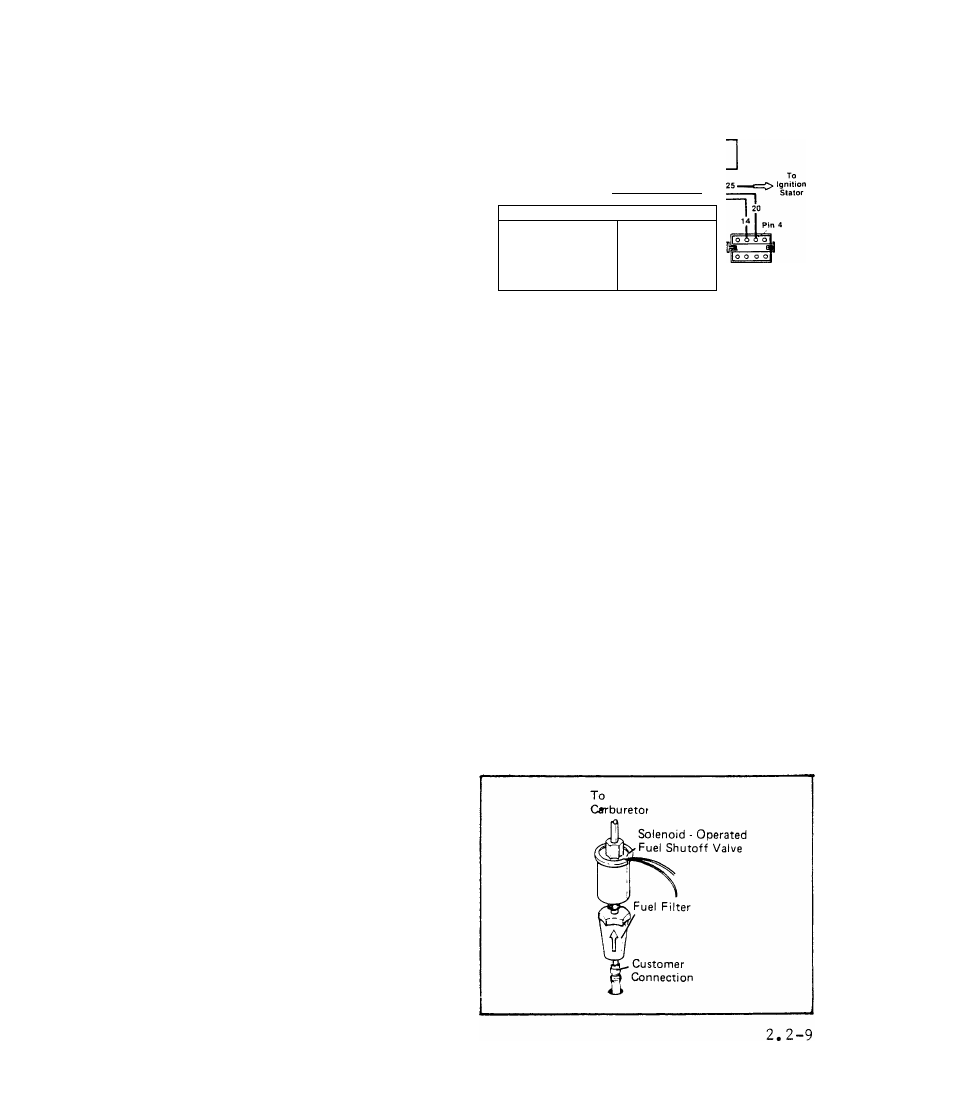
TEST 19:- FUEL FILTER
Remove and replace fuel filter.
Make sure arrow on filter body-
points toward the solenoid oper
ated Fuel Shutoff Valve. Repeat
Test 16 (NO FUEL FLOW).