Generac Power Systems MC User Manual
Page 33
Attention! The text in this document has been recognized automatically. To view the original document, you can use the "Original mode".
C.)- Check Wire No. 14, between Fuel Pump and terminal strip, for open
or shorted condition,
RESULT:- Wire No. 14 checks good............ Continue Diagnostic tests
Wire No. 14 cheeks bad............ Repair/replace Wire No. 14
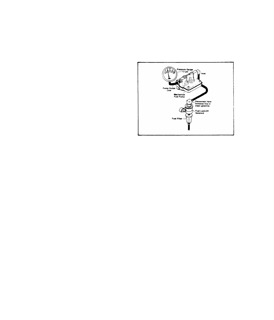
UNITS WITH MECHANICAL FUEL PUMP
Disconnect Piomp Outlet Line at the
carburetor inlet. Connect a press
ure gauge to the line. Disconnect
Pump Inlet Line at the £ue-l lock-
off solenoid and immerse line in
clean gasoline. Crank engine. The
pressure gauge should indicate 1-
3 psi.
RESULT:- Pressure gauge read 1-3 psi........ Continue Diagnostic Tests
Pressure gauge does -not read 1-3 psi........... Replace Pump
TEST 22;- CHECK INSTALLATION
Check alternator installation for:-
1. )- Any other filter screens in the fuel supply line from gas tank.
If other filters are found, check for clogging.
2. )- A Shutoff Valve in the fuel supply line. Make sure Shutoff Valve
is OPEN.
3. )- Anything that might restrict cooling air flow, such as air inlet
or exhaust openings too small, clogged air inlet screening, etc.
If cooling air flow is inadequate, interior compartment tempera
tures will be high resulting in possible fuel line vapor lock,
4. )- Alternator fuel pump located too high above fuel supply tank.
Maximum vertical lift for MC units with an electric pump is app
roximately 18 inches, for mechanical fuel pumps approximately 9
inches.
TEST 23- CARBURETOR
This test covers the procedures for adjustment of the carburetor Idle
Speed Stop Screw, Idle Mixture Adjusting Screw, and High Speed Jet Ad
justing Screw. In addition to these adjustments, the float valve and
its seat should be checked, as well as the float level.
2.2-11