Generac Power Systems MC User Manual
Page 46
Attention! The text in this document has been recognized automatically. To view the original document, you can use the "Original mode".
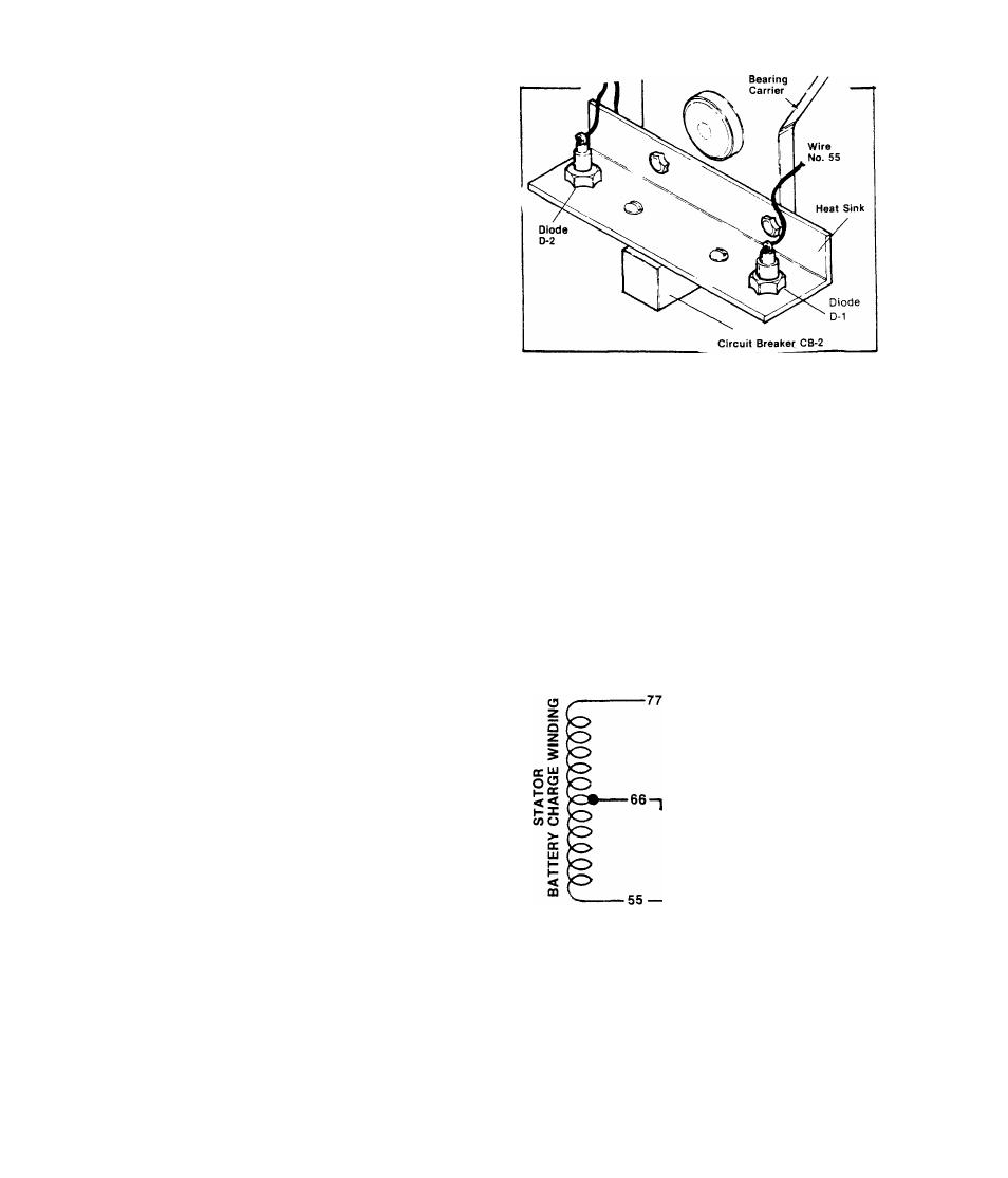
DIODES D1 ANDD2
A.)- Disconnect Wire No. 78 at the
circuit breaker CB-2, Set the VOM
to '*+DC” and to ’’Rxl” scale. Zero
the meter. Connect the positive (+)
test probe to Wire No. 78 from the
Diode D-2. Connect the common (-)
test probe to frame ground. Meter
needle should not move. Set meter
to ”-DC", or reverse the meter test
probes. Meter needle should swing
upscale to some mid-scale reading
(approximately 7-12 Ohms).
RESULT:- Diode D-2 tests good...... Reconnect Wire 78,
Diode D-2 tests bad.... . .... ............
go to Paragraph B
.Replace Diode D-2
B.)- Set VOM to ”+DC” and to ”Rxl” scale, then zero the meter. Connect
the positive (+) test probe to the Diode D-1 terminal end. Connect the
common (-) test probe to frame ground. Meter needle should not move.
Set meter to ”-DC” or reverse the test probes. Meter needle should move
upscale.
RESULT:- Diode D-1 tests good.......................... Continue tests
Diode D-1 tests bad........................ ...Replace Diode D-1
STATOR BATTERY CHARGE WINDINGS
Disconnect Wire 77 from Circuit Break
er CB-2, Unplug the red connector plug
from its receptacle on the stator can.
Set VOM to "+DC” and to ”Rxl" scale,
then zero the meter. Connect one meter
test probe to Wire 55 at the Diode D-1
terminal. Connect second test probe to
Pin 6 of the red receptacle. Meter
needle should swing upscale (approxim
ately ,08 Ohm). Repeat test with meter
test probe connected to red receptacle
Pin 6 and Wire 77 - meter should indi
cate approximately .08 Ohm,
.08 ohm.
.08 ohm.
To
CB-2
Pin 6
€ 0
0 0
00
RED
RECEPTACLE
To
•DIODE D-1
RESULT; Both meter readings were approximately
.08 Ohm............... ...................... ....... Test good
Meter needle did not indicate .08 Ohm.......... Replace stator
2.3-2