Generac Power Systems MC User Manual
Page 41
Attention! The text in this document has been recognized automatically. To view the original document, you can use the "Original mode".
TEST 36:- CHECK VOLTAGE
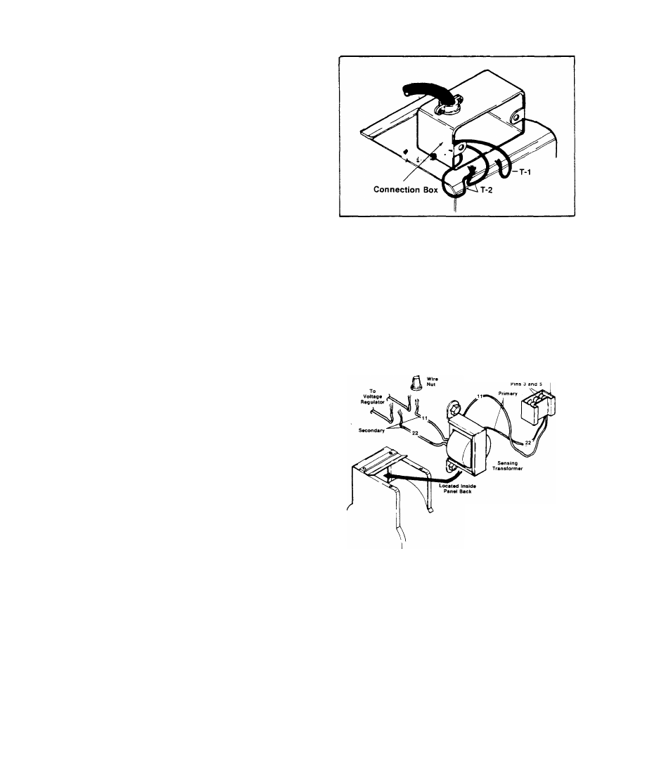
Disconnect customer wiring from
Wires No. T1 and T2 in alternator
connection box. Check a-c voltage
output at Wire No. T1 and junction
of Wires T2. Reading should be ap
proximately 125 Volts a-c at no-load
and 115-125 Volts a-c under load.
RESULT:- Vol.tage output bad,,
Voltage checks good.
.Continue diagnostic tests
.....Check customer wiring
NOTE
Alternators are factory connected to provide a 120 Volt a-c output
only. Some units may have been reconnected to supply 120/240 Volts
a-c. See Page 1.2-3.
TEST 37;- SENSING TRANSFORMER
A./-Remove 2 wire nuts that connect
wires No. 11 and 22, between Sensing
Transformer and Voltage Regulator.
Disconnect the wires. Set VOM to
”+DC” and to ”Rxl00" scale, then ze
ro the meter. Connect meter test
probes across wires No, 11 and 22
from the Sensing Transformer. Meter
needle should swing upscale and indi
cate secondary winding resistance.
See illustration at right.
White Connector Plug
Resistance (± 15%)
Winding Wescoil Coiltran
Primary
785 ohms
969 ohms
Secondary
1886 ohms
1438 ohms
RESULT;- Secondary winding resistance checks good... Go to Paragraph В
Meter needle does not swing upscale....... Replace Transformer
B.)- Unplug the white connector plug from its receptacle on the stator
can. Set VOM to ”-t-DC” and to ”RxlO, 000" scale. Zero the meter. Connect
one meter test probe to white connector plug Pin No. 3. Connect the re
maining probe to white connector plug Pin No. 5, Meter needle should
swing upscale and indicate PRIMARY winding resistance. See illustration
above right.
2.2-19